Method for Improved Selection of Rnai Transfectants

a technology of rnai transfectants and rnai transfectants, which is applied in the field of improved selection of rnai transfectants, can solve problems such as use of markers

Inactive Publication Date: 2008-10-09
F HOFFMANN LA ROCHE & CO AG
View PDF2 Cites 7 Cited by
  • Summary
  • Abstract
  • Description
  • Claims
  • Application Information

AI Technical Summary

Benefits of technology

[0031]In a preferred embodiment, said inactivation of gene expression is a transient inactivation. In the context of the present invention, transient inactivation is being defined as inactivation of expression of a certain gene within a population of cells without applying selective pressure. In this context, enrichment of cells coexpressing the introduced cell surface marker offers the advantage that respective analytical assays can be performed within a few days after the transfection itself. Moreover, transient transfection assays avoid problems of generating stable transformants associated with effects due to growth disadvantages that result from integration events into the host genome.
[0058]Usually, selection by means of an appropriate cell surface protein can be performed already after 16-48 hours, as soon as expression of the cell surface marker occurs. As a consequence, biochemical and phenotypical analysis of cells silenced for target gene expression can be studied rapidly after transfection, which excludes any potential long term artifacts when the cells are grown over multiple generations in tissue culture. Furthermore, selection by means of using an appropriate cell surface protein marker can be repeated several times.

Problems solved by technology

However, usage of EGFP as a selection marker has several draw backs: First, EGFP overexpression may exert cytotoxic effects in transfected cells, with varying degree depending on the cell type used.
Second, since the fluorescence signal of EGFP largely depends on the protein's conformation, which is perturbed by various fixation techniques, this strategy is restricted to applications alleviating fixation of cells.
Third, in cases where silencing of a target gene induces cell death, EGFP is not a useful marker, as cells with damaged membranes fail to retain the soluble EGFP (Chalfie, M., and Kain, S., (eds), in Green Fluorescent Protein: properties, applications and protocols, Wiley-Liss, New York, 1998, and Harvey, K. J., et al., Cytometry43 (2001) 273-278).

Method used


Image

  • Method for Improved Selection of Rnai Transfectants
  • Method for Improved Selection of Rnai Transfectants
  • Method for Improved Selection of Rnai Transfectants

Examples


example 1

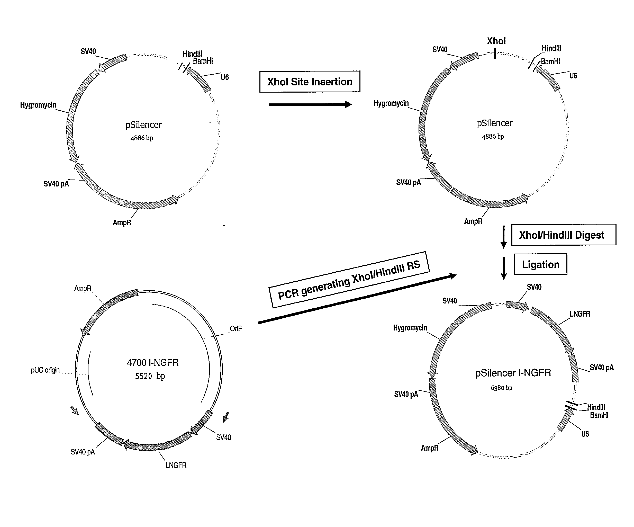
[0080]Cloning Strategy for the Generation of a Vector Encoding Both 1-NGFR and a U6 Promoter Driven shRNA Expression Cassette

[0081]To generate a 1-NGFR vector coexpressing the U6 promoter driven shRNA cassette termed pHC for high-content, the 1-NGFR ORF in context with a SV40 early promoter and polyadenylation sequence was amplified from a 1-NGFR expression vector by PCR using the primers

(SEQ ID NO: 1)pHC_FW 5′-CGCCTCGAGTCCCTGTGGAATGTGTGTCAGTTAG-3′and(SEQ ID NO: 2)pHC_RV 5′-CGCAAGCTTGCTGGCCTTTTGCTCACATGTTC-3′

[0082]The 1-NGFR PCR-fragment was subcloned into pSilencer U6 2.1 Hygro (Ambion) using the HindIII and a unique restriction site for XhoI generated by site-directed mutagenesis (Stratagene). Subsequently, a variety of DNA oligonucleotides (chemically synthesized by Metabion (Germany)) encoding shRNA sequences were annealed and ligated into pHC to generate pHC_luc, pHC_eg5 and pHC_Her2:

luc:(SEQ ID NO: 3)5′-GATCCGCTTACGCTGACTTCGATTCAAGAGATCGAAGTACTCAGCGTAAGTTTTTTGGAA-3′(SEQ ID NO:...

example 2

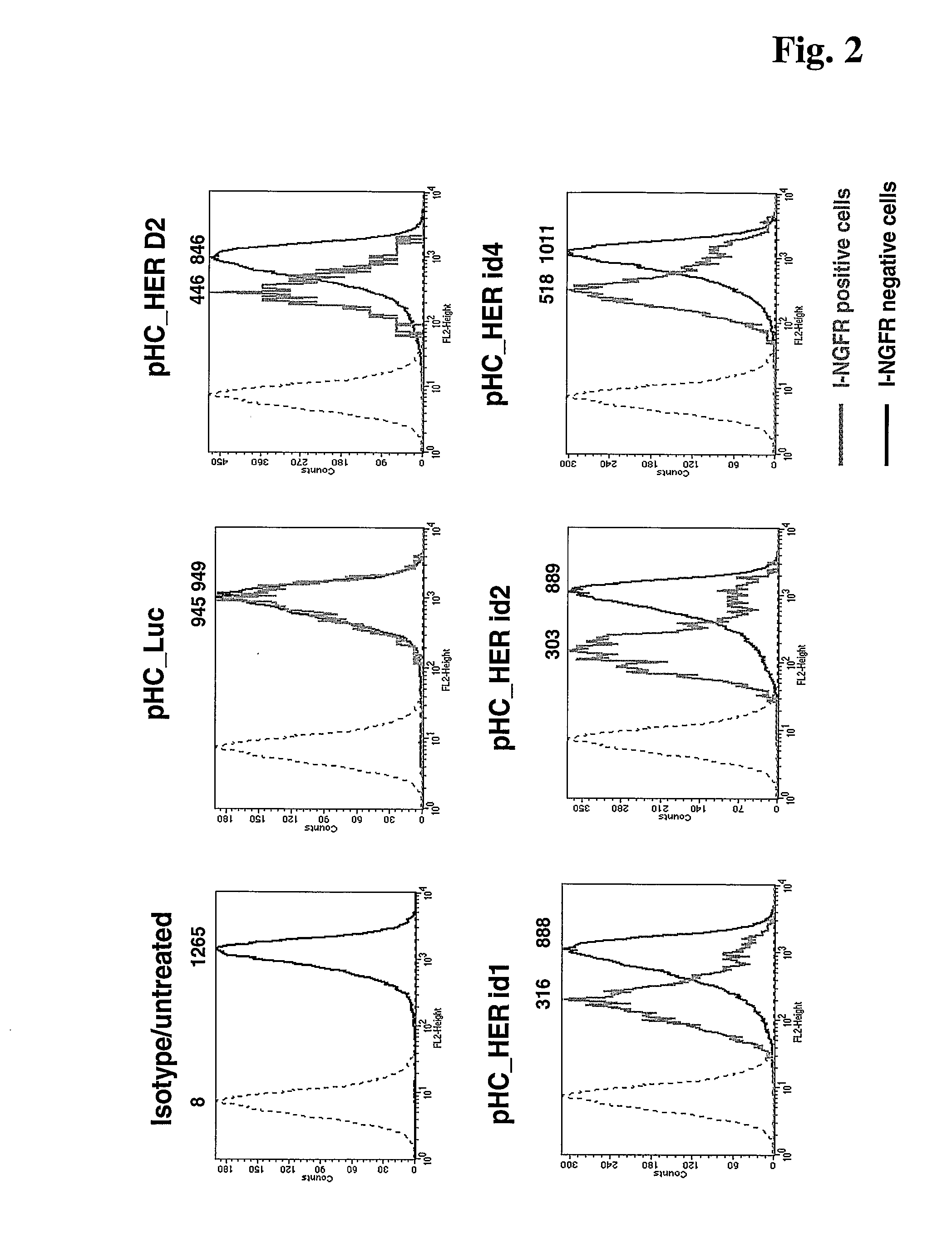
[0084]Knock-Down Efficiency of HER2 Protein that is Expressed on the Cell Surface

[0085]SKBR3 cells were transfected with 4 different pHC_Her2 constructs encoding shRNAs directed against HER2. Transfection with pHC luc targeting luciferase, which is not expressed in these cells, served as negative control. HER2 expression in pHC_luc and pHC_Her Fugene 6 (Roche Diagnostics) transfected cells was determined by staining the cells for HER2 as well as for 1-NGFR followed by flow cytometric analysis. Gating on 1-NGFR positive cells enables exclusive analysis of the transfected cell population. Results are shown in FIG. 2. In the histogram plots black histograms represent HER2 expression of non-transfected (1-NGFR negative) cells and grey histograms represent HER2 expression transfected (1-NGFR positive) cells recorded from the same sample. The dashed graphs in the histogram plot represent isotype control staining. Numbers on the x-axis and above the histograms indicate mean fluorescence in...

example 3

Enrichment of 1-NGFR-Positive Cells by Magnetic Cell Separation (MACS) in Transient Transfection Experiments

[0087]The MACSelect 1-NGFR System (Miltenyi Biotech) was used to enrich 1-NGFR positive cells 96 hrs after transfection according to example 2 of pHC_luc. In the histograms (FIG. 3), 1-NGFR expression of non-transfected cell populations (black curves) was compared to 1-NGFR expression before MACS sorting (upper panel, grey curves) and after MACS sorting (lower panel, grey curves) of pHC_luc transfected cell populations, respectively. Here, 1-NGFR expression was determined by flow cytometric detection of -Microbead labeled cells applying -Alexa488 Ab (Molecular Probes). The number in the histograms indicates the percentage of Microbead labeled cells before and after magnetic cell separation.

[0088]Thus, application of 1-NGFR as reporter offers the unique option to enrich silenced cells via magnetic cell sorting.


PUM

PropertyMeasurementUnit
cell surface proteinaaaaaaaaaa
surfaceaaaaaaaaaa
antibiotic resistanceaaaaaaaaaa

Abstract

The present invention is directed to a method for inactivation of expression of a gene in a eucaryotic cell comprising (i) transfection of a eucaryotic cell with DNA comprising an expression cassette for expression of a cell surface protein and an expression cassette for expression of a RNAi compound, said compound being capable of inactivating expression of said gene, wherein said expression cassette for expression of a cell surface protein and said expression cassette for expression of a RNAi compound are located on the same vector DNA, and (ii) enrichment and / or selection of cells which express said cell surface protein.

Description

[0001]The present invention relates to the field of gene inactivation by means of RNAi. More precisely, the present invention relates to the field of selection principles for enrichment and isolation of cell populations with a respective RNAi mediated gene silencing effect. In particular, the present invention is applicable for functional gene analysis using RNAi for transient and long-term silencing of gene expression in the field of oncology and apoptosis.BACKGROUND PRIOR ART[0002]The phenomenon of RNAi mediated gene silencing has been described first in the Caenorhabditis elegans system, in which microinjection of long double stranded RNA molecules was reported to result in an inactivation of the respective gene (U.S. Pat. No. 6,506,559). Later on, RNAi mediated gene silencing has been disclosed in vertebrates (EP 1 114 784), mammals and in particular human cells (EP 1 144 623). In these systems, gene inactivation is achieved successfully, if short, double stranded RNA molecules ...

Claims


Application Information

Patent Timeline
Patent Type & Authority Applications(United States)
IPC IPC(8): C12Q1/68C12N15/87C12N15/63C12N5/06C07K16/00C12N15/11
CPCC12N15/111C12N2310/111C12N2310/14
Inventor KUBBIES, MANFREDMACEK, ROBERTRIES, CAROLA
Owner F HOFFMANN LA ROCHE & CO AG
Why Eureka
Try Eureka