Light Coupling Adapter Device For Photodynamic Or Photothermal Therapy Or Photodynamic Diagnosis, Corresponding System And Method

a technology of light coupling adapter and photothermal therapy, which is applied in the direction of dianostics using fluorescence emission, radiation therapy, sensors, etc., can solve the problems of contaminated fibres having to be discarded, affecting the optical quality of the fibre, and placing a considerable burden on these organs or systems

US20080249517A1Inactive Publication Date: 2008-10-09SPECTRACURE
31 Cites 43 Cited by

Patent Information

Authority / Receiving Office
US · United States
Patent Type
Applications(United States)
Current Assignee / Owner
Publication Date
2008-10-09
Estimated Expiration
Not applicable · inactive patent

Smart Images

  • Figure 1
    Figure 1
  • Figure 2
    Figure 2
  • Figure 3
    Figure 3
Patent Text Reader

Abstract

A system configured for photodynamic or photothermal therapy and photodynamic diagnosis of a tissue is 5 disclosed. The system comprises in combination an assembly of: a proximal end adapter for a catheter comprising an adapter body (32), having proximal and distal ends, defining an axial lumen extending between the proximal and distal ends, a catheter mounting element at the distal end 10 of the adapter body (32) for sealingly mounting a catheter to the adapter body, and a hollow catheter (31), wherein the catheter mounting element connects a catheter body to the hollow catheter so that the hollow catheter extends from the distal end of the catheter body; a first light 15 guide (36) having proximal and distal ends, wherein said first light guide is sealingly contained in said axial lumen defining an axial optical path extending between the proximal and distal ends of the adapter body (32) towards said tissue (8) and into close proximity thereof or 20 interstitially into said tissue; an optical connector mounting element at the proximal end having mounted an optical connector (37) to the adapter body, and wherein said optical connector (37) is coupled to a light source via a second light guide (38), such that light from said 25 light source is transmittable from said light source via said second light guide (38) and further via said optical connector (37) to said first light guide (36) via said proximal end adapter towards said tissue (8) through said catheter (31).
Need to check novelty before this filing date? Find Prior Art

Description

RELATED APPLICATIONS

[0001] This application claims priority to International Application No. PCT / SE2006 / 050120 filed May, 12, 2006 entitled “Light Coupling Adapter Device For Photodynamic Or Photothermal Therapy Or Photodynamic Diagnosis, Corresponding System And Method,” whih claims priority to Swedish Application No. SE0501077-2 filed May 12, 2005 entitled “Device For Photodynamic Diagnosis Or Therapy,” and U.S. Provisional Application Ser. No. 60 / 680,770 filed May 13, 2005 entitled “Device For Photodynamic Diagnosis Or Therapy,” all of which are hereby incorporated by reference.FIELD OF THE INVENTION

[0002] The present invention relates to a system for interactive interstitial photodynamic or photothermal therapy and / or diagnosis of a tissue by an apparatus having at least one source of therapeutic or diagnostic light, such as a source of laser radiation, and at least one radiation conductor, such as a light guide in the form of an optical fibre, for transmitting light between said ...

Examples

Embodiment Construction

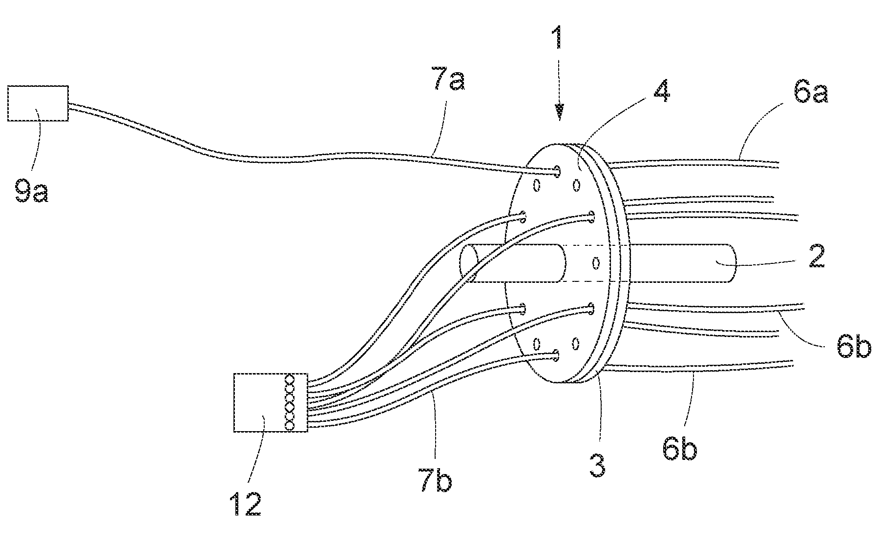
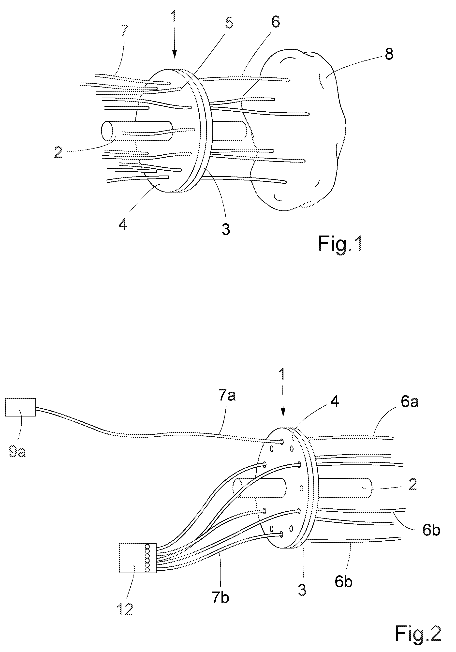
[0061]FIG. 1 is a schematic view of a device for interactive interstitial photodynamic light therapy (PDT) or photo-thermal therapy (PTT) and photodynamic diagnosis (PDD) of a site on and / or in a human being or an animal. A plurality of, or at least two, radiation conductors, such as light guides or optical fibres 6 are directly inserted in a tissue 8, which may be an organ, a tumour or any other tissue. The fibres 6 may be inserted with their distal ends, respectively, in the tissue 8 in a geometric pattern and interstitially. Thus fibres 6 are patient fibres. As shown in FIG. 1, the distal ends of the patient fibres 6 are arranged in a geometric pattern covering a certain area to be investigated and / or treated. The proximal ends of the patient fibres 6 arranged at a distance from the tissue are inserted and attached to a flat disc 3 of a switching means 1, as shown in FIG. 1. The flat disc 3 is arranged adjacent a second flat disc 4 and the flat discs are rotatable in relation to ...