Air Vaporizer and Its Use in Base-Load LNG Regasification Plant

Inactive Publication Date: 2008-10-16
CONOCOPHILLIPS CO
View PDF18 Cites 99 Cited by
  • Summary
  • Abstract
  • Description
  • Claims
  • Application Information

AI Technical Summary

Benefits of technology

[0045]The present invention enables the practical use of air vaporizers in a wider range of weather conditions and geographical locations for LNG regasification plants. The use of a plurality of such improved regasification units can be suitable in base-load LNG regasification facilities, as the regeneration mode (e.g., defrosting) can be efficiently carried out regardless of the ambient air conditions, by heating (when needed in an intermittent fashion) the ambient air entering the air vaporizer for effective defrosting. Indeed, during defrosting of the air vaporizer, the intermittent heating of the ambient air

Problems solved by technology

However, when distance and terrain make a pipeline impossible or non-economical, natural gas must be transported by other means.
A key cost factor for the operations of import terminals is the process of vaporizing LNG into natural gas, which is also known as LNG regasification.
Submerged combustion vaporization and open-rack vaporization are the most common LNG vaporization methods and are both proven, but they also carry high operating costs and environmental-emissions burdens.
The SCV method generally spends 1.3 to 1.5% of the generated natural gas, which is a significant operating cost and further generates greenhouse gases such as carbon dioxide.
The ORV method must use a large daily amount of ambient water (e.g., hundreds of millions of gallons a day), which may cause a change in ambient water temperature of a few degrees in the vicinity of the effluent discharge of the vaporization unit.
Forced convection includes additional costs for power and maintenance.
Despite the lower energy demand and reduction of environmental-emissions issues with ambient air

Method used


Image

  • Air Vaporizer and Its Use in Base-Load LNG Regasification Plant
  • Air Vaporizer and Its Use in Base-Load LNG Regasification Plant
  • Air Vaporizer and Its Use in Base-Load LNG Regasification Plant

Examples


Example

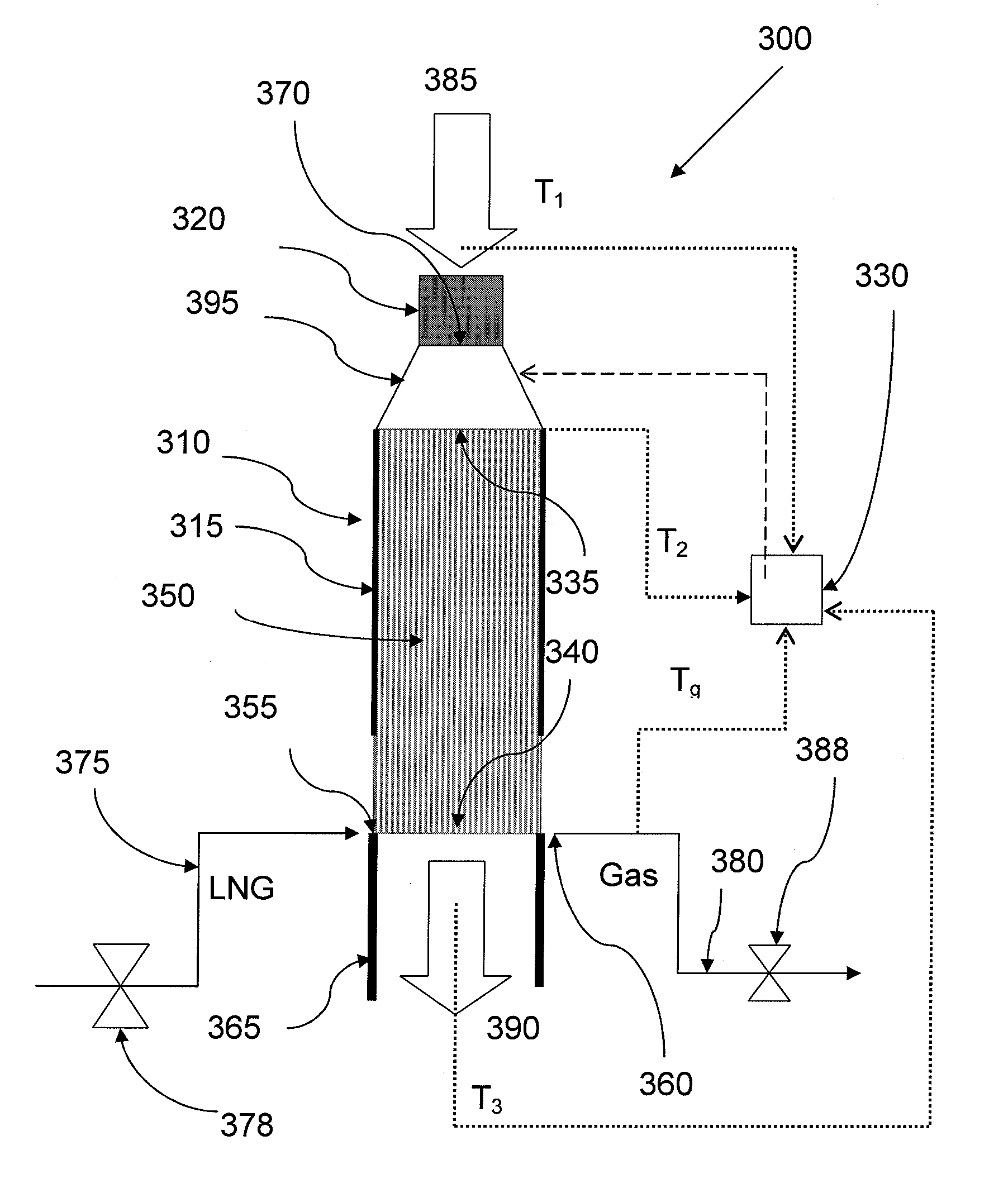
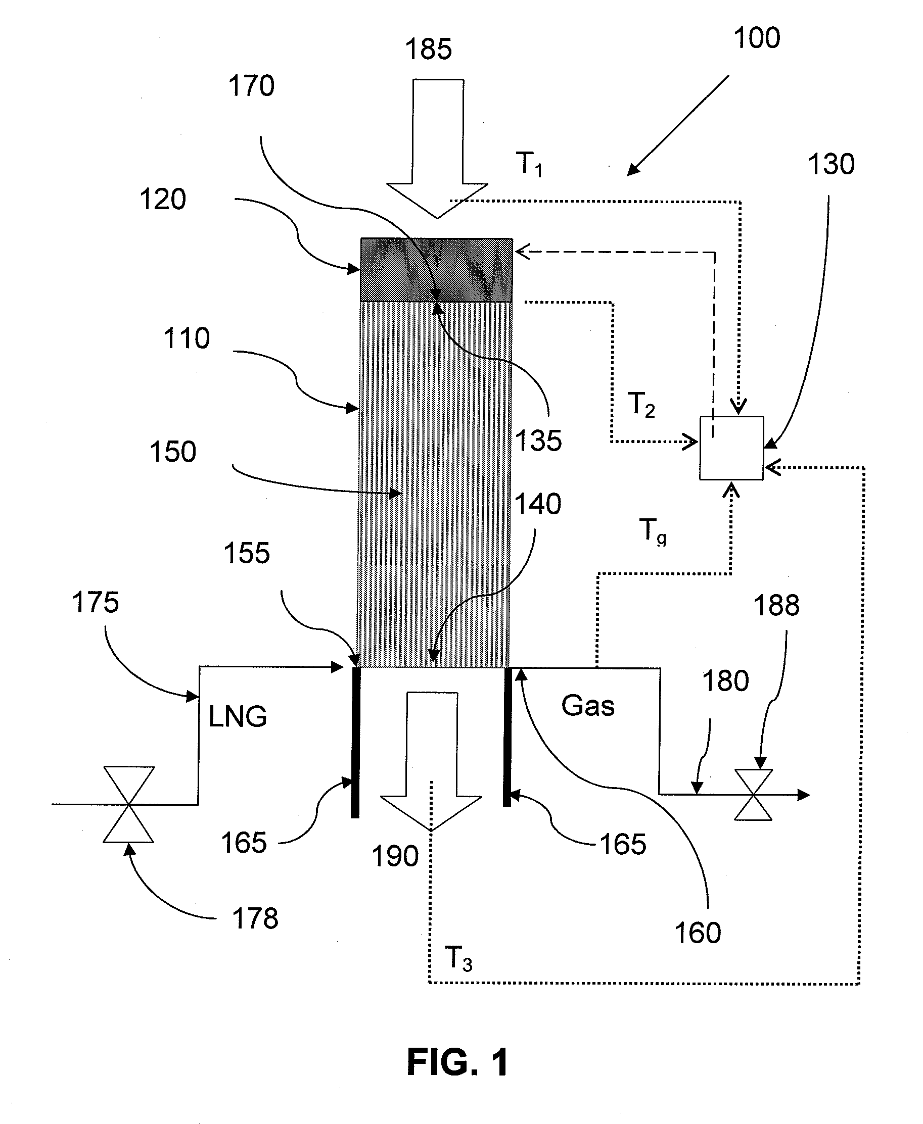
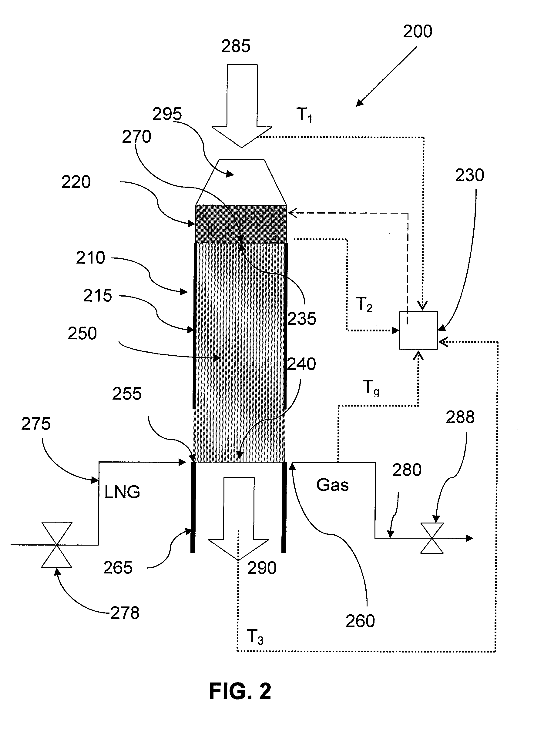
[0055]The present invention relates to processes for the vaporization of cryogenic fluid to gas, particularly to regasification of liquefied natural gas, and is susceptible to embodiments of different forms. There are shown in the drawings, and herein will be described in detail, specific embodiments of the present invention with the understanding that the present disclosure is to be considered an exemplification of the principles of the invention, and is not intended to limit the invention to that illustrated and described herein.

[0056]In the description that follows, like parts are marked throughout the specification and drawings with the same reference numerals, respectively. The drawing figures are not necessarily to scale. Certain features of the invention may be shown exaggerated in scale or in somewhat schematic form and some details of conventional elements may not be shown in the interest of clarity and conciseness.

[0057]It is to be fully recognized that the different teach...


PUM


Abstract

A system and method for production of gas from a cryogenic fluid using an improved air vaporizer in cyclic production/regeneration modes with a forced air draft and an intermittent heating of ambient air entering the air vaporizer during regeneration mode and/or optionally during the production mode. The system and method may be used in geographical areas where the ambient air temperature can be below freezing. Particularly, the system and method may employ a plurality of these improved air vaporizers for regasification of liquefied natural gas (LNG), particularly for continuous production of natural gas in a base-load LNG regasification plant.

Description

CROSS-REFERENCE TO RELATED APPLICATIONS[0001]Not Applicable.STATEMENT REGARDING FEDERALLY SPONSORED RESEARCH OR DEVELOPMENT[0002]Not applicable.TECHNICAL FIELD OF THE INVENTION[0003]This invention relates to an improved air vaporizer for the vaporization of cryogenic fluids and to a method for vaporizing a cryogenic fluid to gas. More specifically, this invention relates to the use of the improved air vaporizer for liquefied natural gas (LNG) regasification, particularly for continuous production of natural gas in a year-round base-load LNG regasification plant using a plurality of the improved air vaporizers in cyclic production / regeneration modes and in all geographical areas, including where the ambient air temperature may be below freezing.BACKGROUND OF THE INVENTION[0004]Natural gas is used in many parts of the world as a principal fuel source for the generation of electricity, for industrial applications, as well as for domestic applications such as heating and cooking. Natura...

Claims


Application Information

Patent Timeline
IPC IPC(8): F17C9/02
CPCF17C9/02F17C2227/0311F17C2227/0313F17C2227/0393F17C2265/05F17C2270/0136
Inventor KATDARE, VIDYADHAR Y.MUELLER, JEFFREY L.
Owner CONOCOPHILLIPS CO
Why Eureka
Try Eureka