
Ion implantation apparatus and ion implantation method

a technology of ion beam and ion beam, which is applied in the field of ion beam implantation apparatus and an ion beam implantation method, can solve the problems of difficult to be dealt, difficult to achieve high speed evacuation and temporary evacuation in an extremely short time period of ion beam, and difficult design in view of the effect of ion beam

Active Publication Date: 2008-10-16
SENCORP
View PDF7 Cites 19 Cited by
  • Summary
  • Abstract
  • Description
  • Claims
  • Application Information

AI Technical Summary

Benefits of technology

[0010]The present invention has been carried out in view of such a problem and it is an object thereof to provide an ion implantation apparatus and an ion implantation method capable of realizing high speed evacuating and temporary evacuating of an ion beam regardless of a diameter or a sectional shape of the ion beam and without effecting an influence on a peripheral member.
[0012]According to the ion implantation apparatus of the present invention, when the deflecting apparatus is brought into a deflecting operation state, the ion beam is brought into an evacuated state by being deflected from a beam trajectory line. Thereby, the ion beam does not advance to a downstream side of the mass analysis slit, and therefore, in a case in which the ion beam is evacuated when, for example, a discharge phenomenon is detected to be brought about, ions by a nonuniform ion beam by the discharge phenomenon can be prevented from being implanted to the wafer. Thereafter, in a case in which the ion beam is released from being evacuated when the discharge phenomenon is not brought about, ion implantation can be restarted.
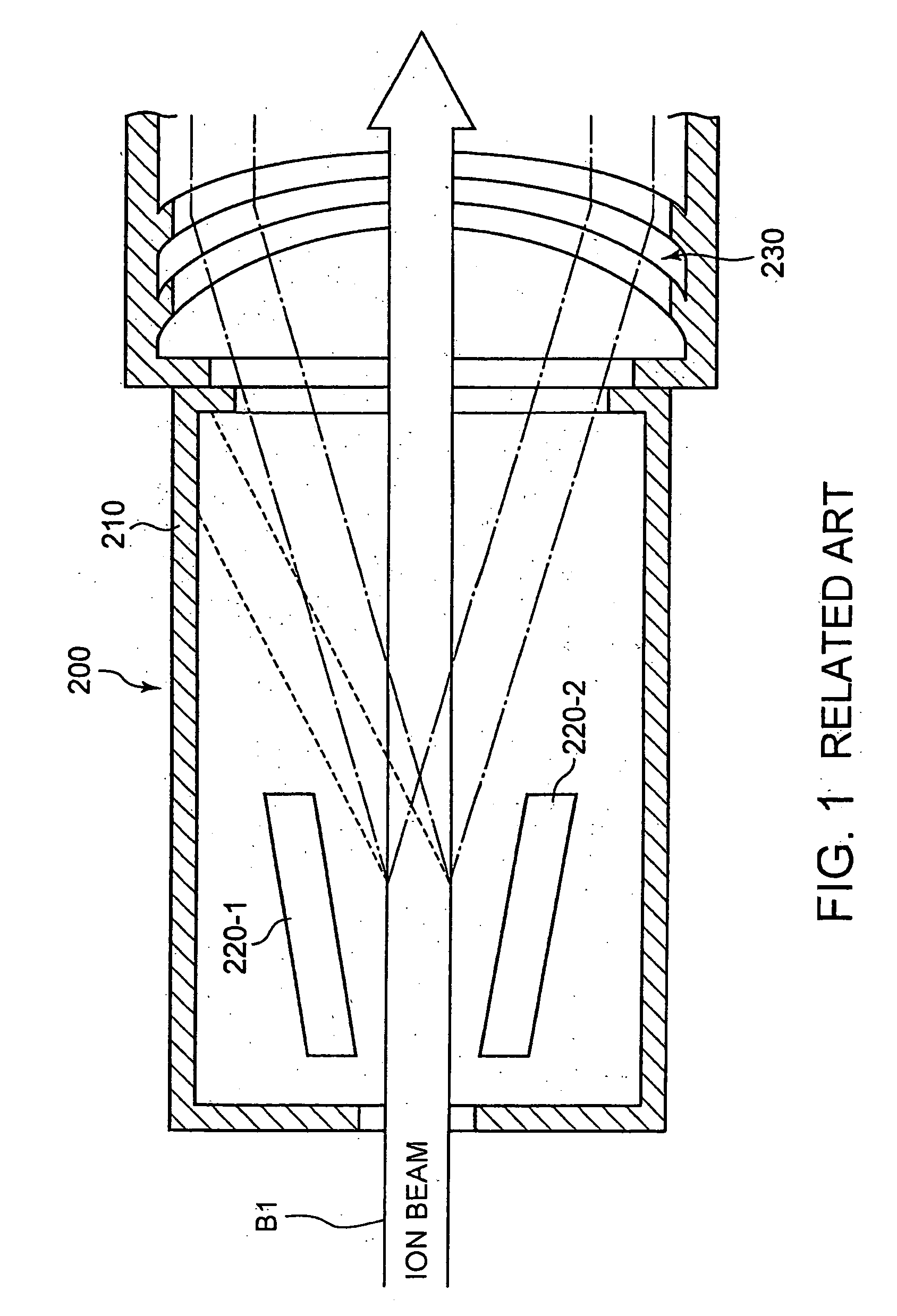
[0024]According to the present invention, the high speed evacuating and temporary evacuating of the ion beam can be realized regardless of a beam diameter or a beam sectional shape of the ion beam without effecting an influence on a peripheral member on the beam line.

Problems solved by technology

Further, it is difficult in view of design to ensure a location of evacuating the ion beam and an influence of irradiating a large diameter ion beam of sputtering the peripheral member or the like is considerable which is difficult to be dealt with.
According to the method, the injector flag Faraday cup is mechanically inserted to the beam line, and therefore, high speed evacuating and temporary evacuating in an extremely short time period of the ion beam is difficult to be realized.

Method used


Image

  • Ion implantation apparatus and ion implantation method
  • Ion implantation apparatus and ion implantation method
  • Ion implantation apparatus and ion implantation method

Examples


Embodiment Construction

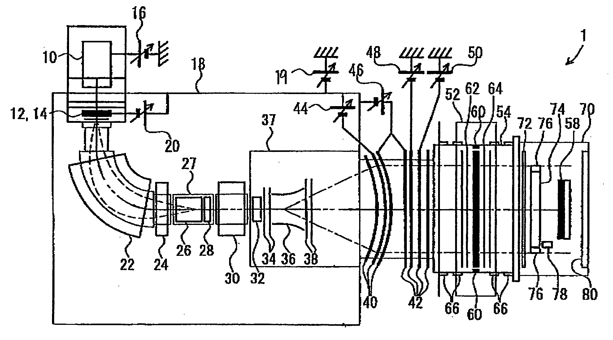
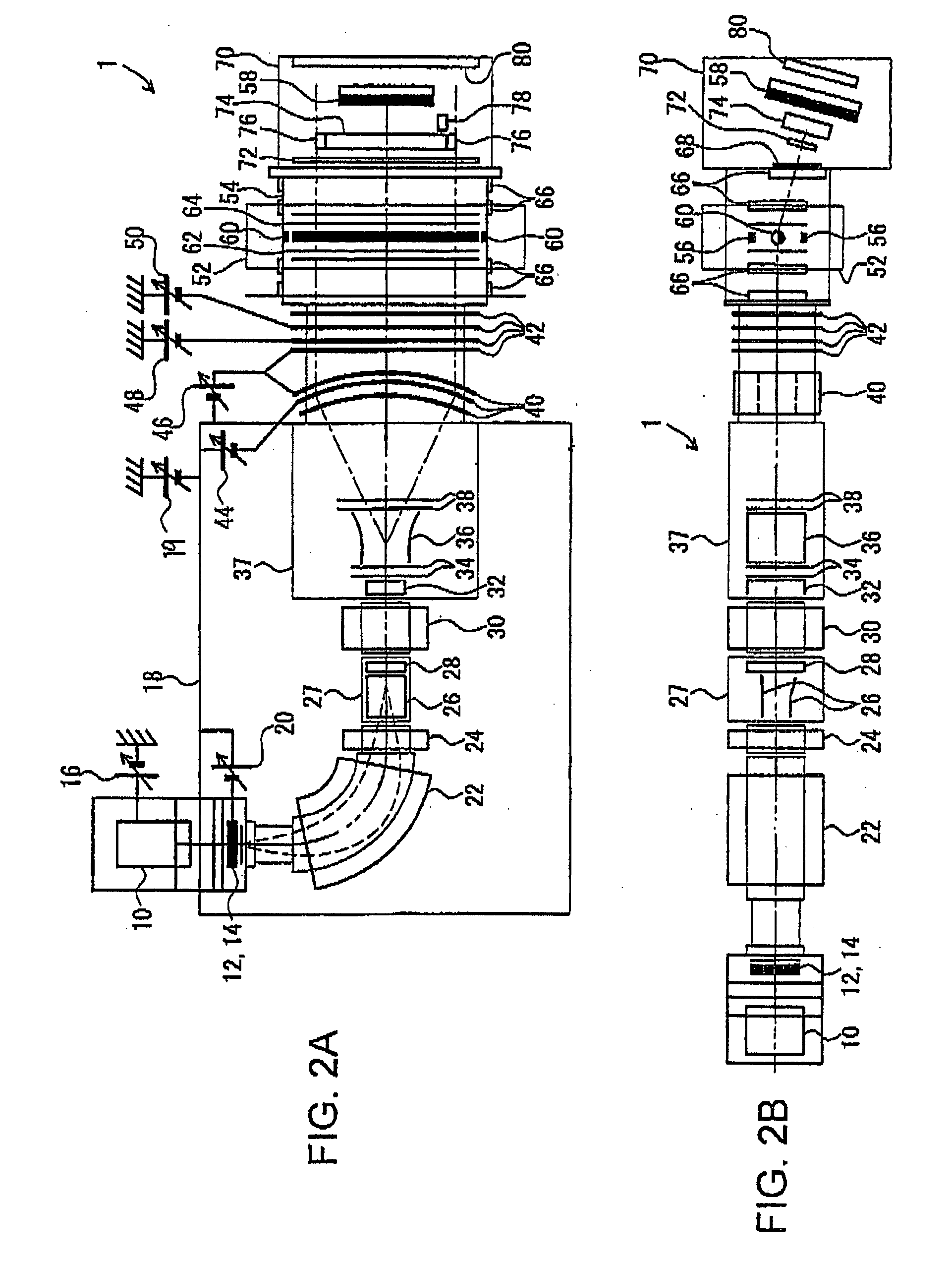
[0038]An embodiment of an ion implantation apparatus according to the present invention will be explained in reference to the drawings as follows. FIG. 2A and FIG. 2B are schematic views when the present invention is applied to an ion implantation apparatus of a single wafer type, particularly, FIG. 2A is a plane view and FIG. 2B is a side view. A constitution of the ion implantation apparatus 1 will be explained from the most upstream side of a beam line constituting a start point by an ion source 10. An outlet side of the ion source 10 is provided with an extracting electrode 12 for extracting an ion beam from a plasma generated at inside of an ion chamber. A vicinity of a downstream side of the extracting electrode 12 is provided with a suppression electrode 14 for restraining an electron included in the ion beam extracted from the extracting electrode 12 from flowing back to the extracting electrode 12. The ion source 10 is connected with an ion source high voltage power source ...


PUM


Abstract

An ion implantation apparatus according to the invention includes a park electrode as a deflecting apparatus arranged at a section of a beam line from an outlet of a mass analysis magnet apparatus to a front side of a mass analysis slit for deflecting an ion beam in a predetermined direction of being deviated from a beam trajectory line by an operation of an electric field. When the ion beam does not satisfy a desired condition, a park voltage is applied to the park electrode, thereby, the ion beam is brought into an evacuated state by being deflected from the beam trajectory line. As a result, the ion beam cannot pass through the mass analysis slit, and therefore, the ion beam which does not arrive at a wafer to prevent the ion beam which does not satisfy the condition from being irradiated to the wafer.

Description

[0001]This application is based upon and claims the benefit of priority from Japanese patent application No. 2007-103194, filed on Apr. 10, 2007, the disclosure of which is incorporated herein in its entirety by reference.FIELD OF THE INVENTION[0002]The present invention relates to an ion implantation apparatus, particularly relates to an ion implantation apparatus and an ion implantation method having a mechanism of extracting an ion beam comprising ions having a desired mass by a mass analysis magnet apparatus, thereafter, evacuating the ion beam by deflecting the ion beam from a beam trajectory line as necessary.DESCRIPTION OF THE RELATED ART[0003]As a method of forming a conductive layer of an n type or p type at a semiconductor wafer, there is used a so-called ion implantation technology for accelerating ions generated by an ion source to be implanted to a wafer as an ion beam. According to the ion implantation technology, an ion beam comprising ions having a desired mass is ex...

Claims


Application Information

Patent Timeline
Patent Type & Authority Applications(United States)
IPC IPC(8): B01D59/44G21K5/10
CPCH01J37/045H01J37/304H01J37/3171H01J2237/31703H01J2237/151H01J2237/30455H01J2237/0213H01J37/317
Inventor TSUKIHARA, MITSUKUNIYAGITA, TAKANORISOGABE, HIROSHIYUMIYAMA, TOSHIOKABASAWA, MITSUAKI
Owner SENCORP
Learn More