Thermal infrared solid state imaging device and infrared camera
a solid-state imaging and infrared technology, applied in the field of infrared solid-state imaging devices and infrared cameras, can solve the problems of difficult low-voltage drive, inability to reduce sensitivity deviation to zero, and pronounced sensitivity deviation, so as to shorten the integration time, improve the integration effect, and reduce the noise
- Summary
- Abstract
- Description
- Claims
- Application Information
AI Technical Summary
Benefits of technology
Problems solved by technology
Method used
Image
Examples
embodiment 1
1. Structure of Thermal Infrared Solid State Imaging Device
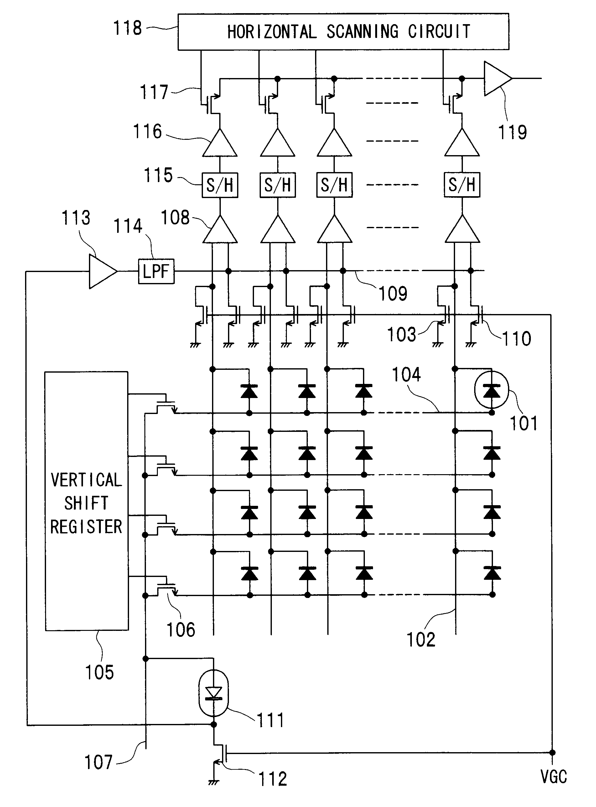
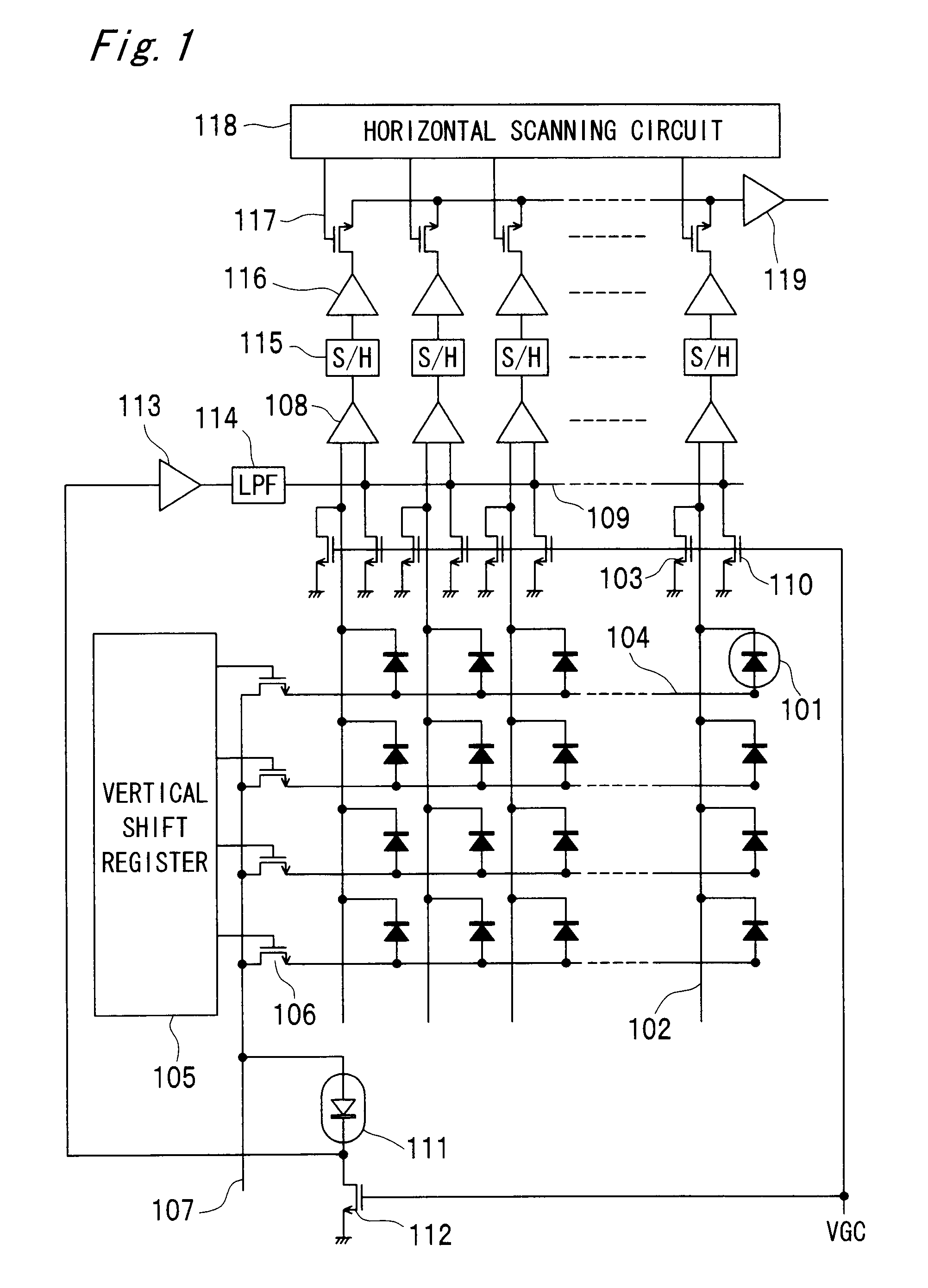
[0038]FIG. 1 is a circuit diagram of the thermal infrared solid state imaging device according to a first embodiment of the invention.
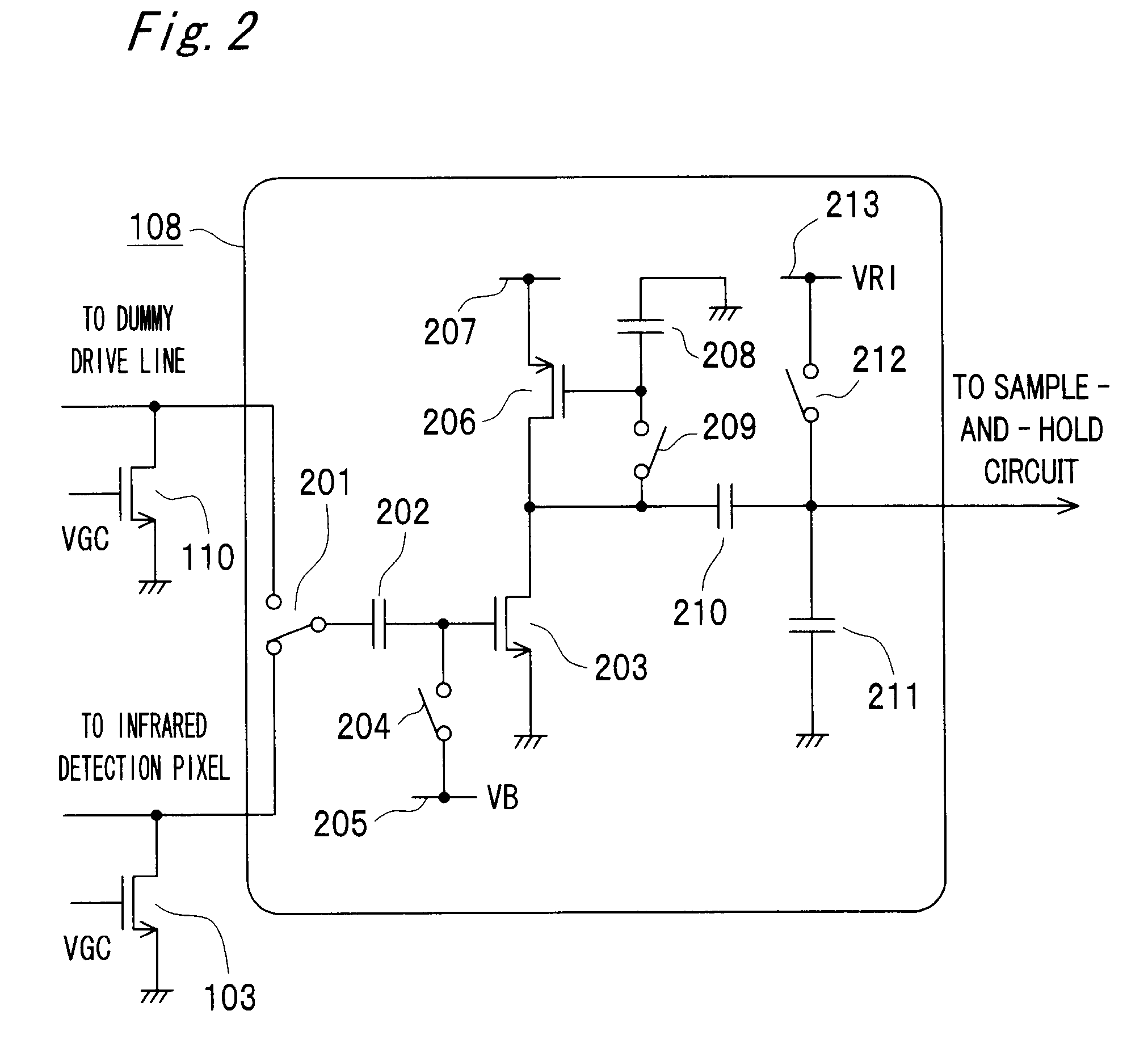
[0039]An infrared detection pixel 101 includes a heat-insulated diode. The infrared detection pixels 101 are arranged in a two-dimensional pixel matrix, forming a pixel area. The cathode of each infrared detection pixel 101 (diode) is connected in common by column to a vertical signal line 102, and a transistor 103 is connected to the end of each vertical signal line 102. The gates of the transistors 103 are connected in common, and a bias voltage VGC for operating in the saturation range is applied to the gates. The transistor 103 thus operates as a constant current source that supplies a constant current to the infrared detection pixel 101. The anodes of the infrared detection pixels 101 are connected in common by row by a horizontal signal line 104. The ends of the horizontal signal lines 1...
embodiment 2
[0074]FIG. 7 is a circuit diagram of a thermal infrared solid state imaging device according to a second embodiment of the invention. This embodiment applies the difference integration circuit described in the first embodiment to the infrared solid state imaging device taught in JP-A-2005-214639 which was previously filed by the applicant of the present application. The reference pixels 111 are disposed at the ends of the horizontal pixel lines in this embodiment of the invention.
[0075]A sample-and-hold circuit 701 samples the output of the reference pixel 111 that is output via the output amplifier 119. A bias generating circuit 702 compares the output from the sample-and-hold circuit 701 with a reference voltage Vref, outputs a decreasing voltage if the output of the reference pixel becomes greater than the reference voltage Vref, and outputs an increasing voltage if the reference pixel output becomes less than the reference voltage. The output voltage is applied through the low-p...
embodiment 3
[0078]FIG. 9 is a circuit diagram of a thermal infrared solid state imaging device according to a third embodiment of the invention. This embodiment applies the difference integration circuit described in the first embodiment to the infrared solid state imaging device taught in JP-A-2005-236717 which was previously filed by the applicant of the present application. In this embodiment, no reference pixel is used, and the entire pixel area is composed of infrared detection pixels 101.
[0079]FIGS. 10A and 0B are schematic diagrams of infrared cameras that use the infrared solid state imaging device according to the present embodiment.
[0080]The infrared camera shown in FIG. 10A has an infrared solid state imaging device 1004, a lens 1003, a pre-amplifier 1005, an A / D converter 1006, a digital signal processor (DSP) 1007, and D / A converter and amplifier circuit 1008. The lens 1003 focuses infrared light emitted by a subject on the infrared solid state imaging device 1004. The pre-amplifie...
PUM
 Abstract
Description
Claims
Application Information
 - R&D
- Intellectual Property
- Life Sciences
- Materials
- Tech Scout
- Unparalleled Data Quality
- Higher Quality Content
- 60% Fewer Hallucinations
Browse by: Latest US Patents, China's latest patents, Technical Efficacy Thesaurus, Application Domain, Technology Topic, Popular Technical Reports.
© 2025 PatSnap. All rights reserved.Legal|Privacy policy|Modern Slavery Act Transparency Statement|Sitemap|About US| Contact US: help@patsnap.com


