
Method and a System for the Assessment of Samples

Active Publication Date: 2008-10-16
CHEMOMETEC AS
View PDF15 Cites 19 Cited by
  • Summary
  • Abstract
  • Description
  • Claims
  • Application Information

AI Technical Summary

Benefits of technology

[0023]It was found that it is possible to perform assessment of chemical and / or physical properties of a sample or sample material with substantial simplification of methods and systems currently used according to the state of the art in the field, furthermore without substantial reduction in the statistical quality of the assessment compared to assessments conducted according to state of the art methods using state of the art systems. Indeed several embodiments of the present invention offer substantial advantage compared to the current methods, and several preferred embodiments of the present invention make it feasible to perform assessments hitherto not feasible using the methods and system of the state of the art in the field.
[0105]These properties offer obvious advantages to an instrument producer, allowing the construction of more simple instruments for assessment based on spectral interference such as interferometers. Also the advantage to the user of instruments based on the present invention is obvious due to improved applicability (e.g. mechanical stability) of such instruments with little or no loss of performance, compared to the state of the art instruments.

Problems solved by technology

The Michelson Interferometer is based on separating a beam of light and then recombining the two beams after a path difference has occurred, thus causing interference in the detected light.
Modern production techniques and computers have been essential in the increasing application of FT spectroscopy, since mechanical and electronical design and construction of such instruments is complicated and requires high precision and sometimes exotic materials.
Transfer of calibration is obviously of interest, since reference samples with accurately known reference values for components of interest are often difficult and expensive to obtain.
One general draw back of several spectrophotometric techniques, including FT spectrophotometers, is the relatively high level of mechanical complexity and physical size.
Demands from industry, for more rugged instruments, suited for installation in the hostile industrial environment are therefore not easily fulfilled.
This is partly due to the inherent simplicity of interpreting univariate correlations and partly due to the difficulty of performing complex manual calculations.
On the other hand, the observed interferogram can be influenced by other sources of information beside spectral information, such as temperature, time dependent electrical noise to mention a few, and under these conditions the inclusion of all information can have destructive information on the quality of the assessment.

Method used


Image

  • Method and a System for the Assessment of Samples
  • Method and a System for the Assessment of Samples
  • Method and a System for the Assessment of Samples

Examples


example 1

A Michelson Interferometer

[0147]The Michelson interferometer is a device that can divide a beam of light (electromagnetic radiation) into two paths and then recombine the two beams. If the two beams travel exactly the same distance between they are recombined all spectral elements of the light are preserved. If on the other hand there is a different in the distance that the two beams have travelled then an interference of certain spectral elements occurs.

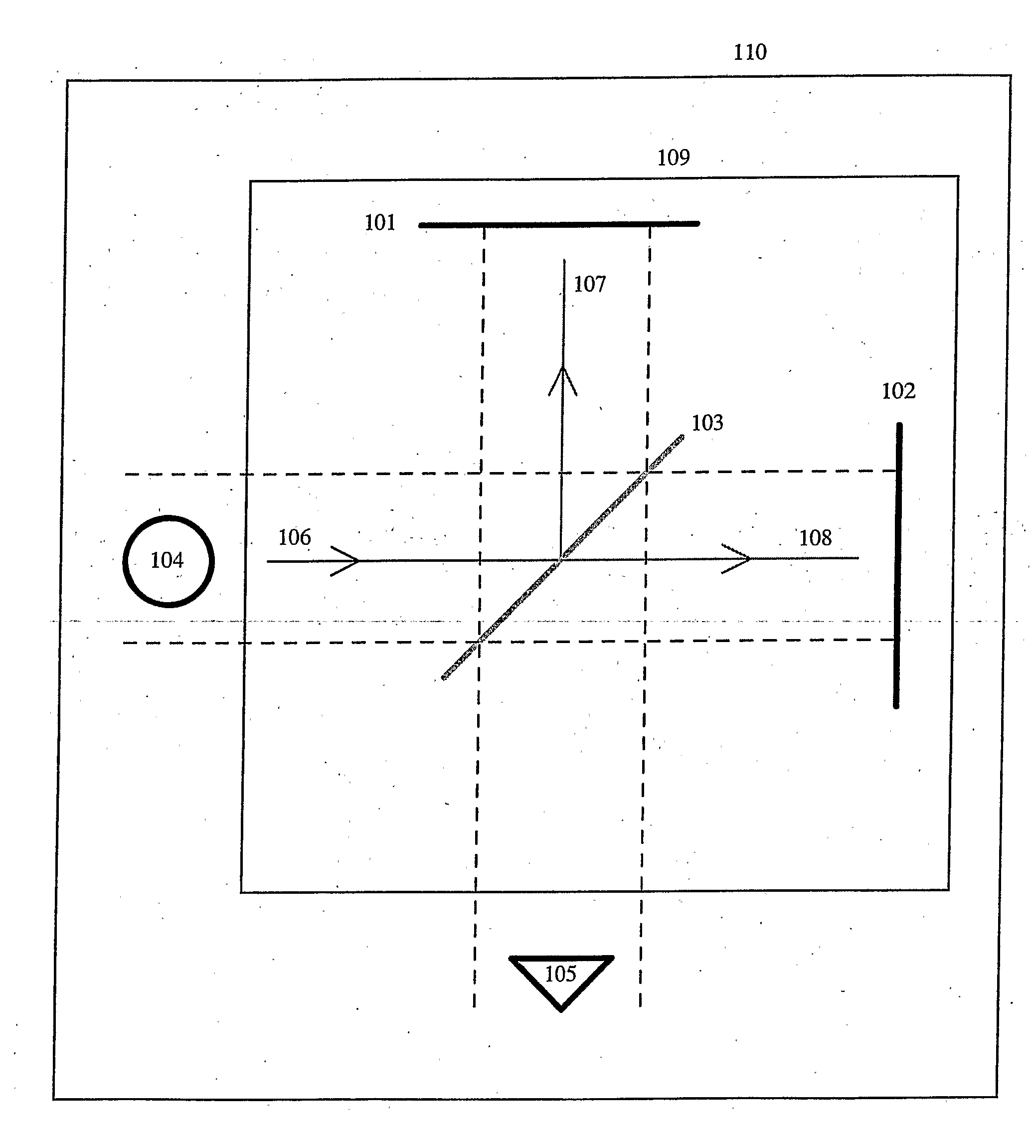
[0148]FIG. 1 illustrates a Michelson interferometer. A typical construction consists of two mirrors 101 and 102, a beamsplitter 103, light source 104 and detector 105. Light from the light source 106 reaches the beamsplitter where it is divided up into two beams, one which is reflected by the beamsplitter 107 and one which is transmitted through the beamsplitter 108. Both these beams are reflected from the respective mirrors and recombine on the beamsplitter and reflected on the detector (not illustrated in the figure).

[0149]Assumin...

example 2

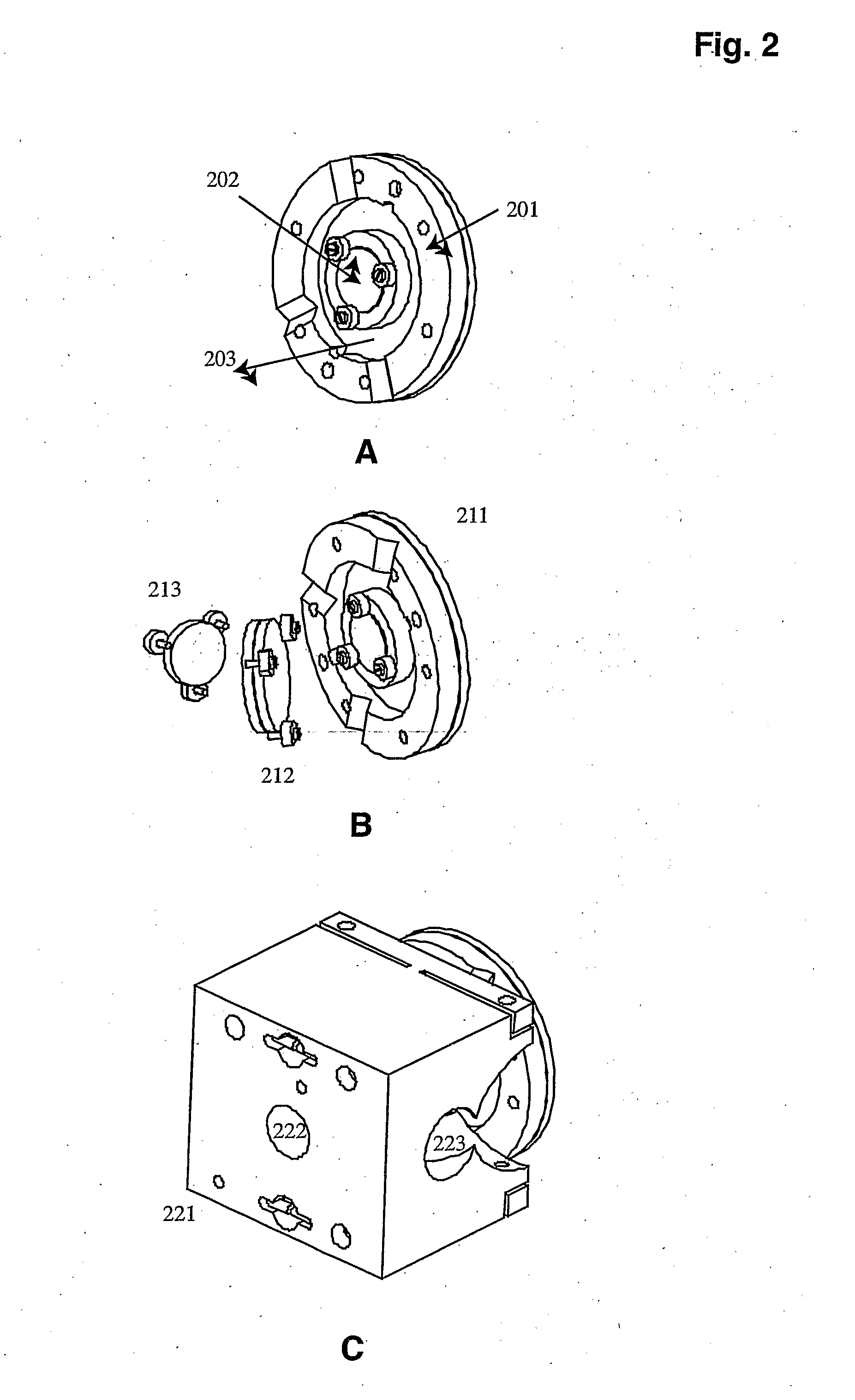
[0155]A Michelson Interferometer According to the Present Invention FIG. 2 illustrates a construction of a “solidMichelson interferometer according to the present invention. The construction of a movable mirror is shown in FIG. 2A, where 201 is a frame on which a diaphragm piezo actuator 203 is attached (Piezomechanik Dr. Lutz Pickelmann GmbH, Germany). A mirror 202 is attached to the centre of the actuator.

[0156]The relative arrangement of the optical components of the interferometer is shown in FIG. 2B. The figure shows the movable mirror 211 and fixed mirror 213 and in between them a beam splitter 212.

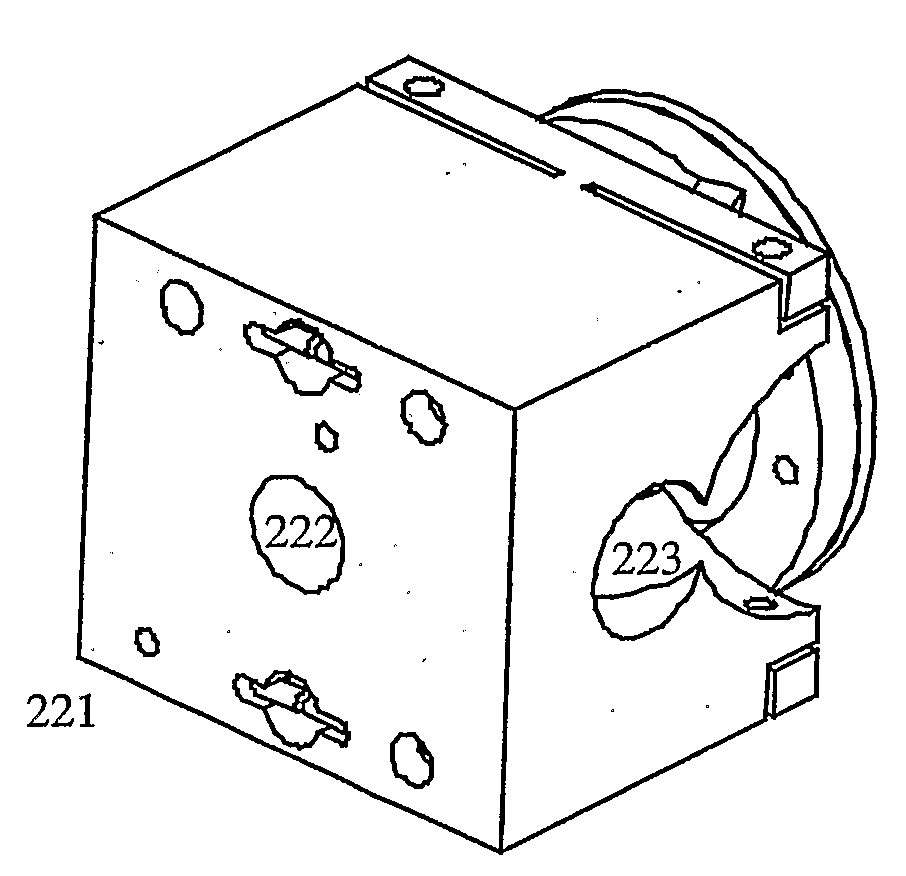
[0157]Finally FIG. 2C shows a block of about 4×4×4 cm 221, in which the optical components are fixed. 222 illustrates the entrance of light (from a light source not shown) and 223 shows the exit of modulated light towards a detector (not shown). Further the block contains arrangement for the engagement of means for aligning of the mirrors (not shown).

[0158]The interferometer descr...

example 3

A Fabry-Perot Interferometer According to the Present Invention

[0169]FIG. 3 illustrates a construction of a “solid” Fabry-Perot interferometer according to the present invention. The design an arrangement of the transparent mirror elements 301 and 302 is shown in FIG. 3A. The mirror elements are triangular in shape, and rotated 60 degrees relative to each other.

[0170]FIG. 3B shows a fixture 311, onto which one of the mirror elements is attached. Further a diaphragm piezo actuator 312 (Piezomechanik Dr. Lutz Pickelmann GmbH, Germany) is attached to the other mirror element. The actuator is attached to a rim 313.

[0171]FIG. 3C shows the casing of the interferometer, where 321 is a house, onto which the actuator and rim is attached. Further, three bolts 322 attach the fixture to the housing, allowing adjustment of the fixture, and thus mirror element 301 relative to the other actuator and thus the mirror element 302.


PUM


Abstract

The present invention offers an alternative strategy for the correlation of interference information to chemical and / or physical properties of a sample. This strategy can be implemented in a method and a system, which offer substantial technical and commercial advantages over state of the art techniques based on interference spectroscopy. The invention further provides a method for standardizing an interferometer, as well as a method and a system using the standardized

Description

FIELD OF THE INVENTION [0001]The present invention relates to a method and a system for the assessment of at least one chemical and / or physical property of a sample or a specimen using spectroscopic techniques based on interferometry.DESCRIPTION OF THE RELATED ART [0002]Spectroscopic techniques, based on modulation have been known for several years. One of these techniques was designed by Michelson in 1891 (A. A. Michelson, Phil. Mag. (5), 31, 256, 1891) and generally referred to as “The Michelson Interferometer”. Michelson interferometers are presently widely implemented in several commercial spectroscopic instruments for infrared measurement (ABB-Bomem Inc. USA, PerkinElmer Inc. USA, Thermo Nicolet USA, Foss Analytical Denmark). The Michelson Interferometer is based on separating a beam of light and then recombining the two beams after a path difference has occurred, thus causing interference in the detected light. Another spectroscopic method based on interferences of light is Fa...

Claims


Application Information

Patent Timeline
IPC IPC(8): G01J3/45G01B9/02G01J3/453G01N21/35
CPCG01J3/0202G01J3/45G01J3/453G01N21/35G01N21/359G01N2021/3595G01N2201/0691G01N2201/129G01N21/3563G01N21/3577G01J3/28G01J3/433
Inventor ARNVIDARSON, BORKURLARSEN, HANS
Owner CHEMOMETEC AS
Features
  • Generate Ideas
  • Intellectual Property
  • Life Sciences
  • Materials
  • Tech Scout
  • Unparalleled Data Quality
  • Higher Quality Content
  • 60% Fewer Hallucinations
Learn More