Method for optically testing semiconductor devices

a semiconductor device and optical testing technology, applied in the direction of measurement devices, semiconductor/solid-state device testing/measurement, instruments, etc., can solve the problems of limiting the effective use of low-frequency external input or output circuit responses, electrical probes suffering from measurement dilemmas, and the characteristic impedance of such lines restricting the use of input/output connections

Inactive Publication Date: 2008-10-16
ATTOFEMTO
View PDF2 Cites 30 Cited by
  • Summary
  • Abstract
  • Description
  • Claims
  • Application Information

AI Technical Summary

Problems solved by technology

In addition, the probe also determines an instrument's ability to probe the integrated circuit due to its size (limiting its spatial resolution) and influence on circuit performance (loading of the circuit from its characteristic and parasitic impedances).
The parasitic impedances and the relatively large probe size compared to integrated circuit interconnects limit their effective use to low-frequency external input or output circuit responses at the bond pads.
Therefore, electrical probes suffer from a measurement dilemma.
The low characteristic impedance of such lines limits their use to input/output connections.
High-impedance probes suitable for probing intermediate circuit nodes have significant parasitic impedances at microwave frequencies, severely perturbing the circuit operation and affecting the measurement accuracy.
In both cases, the probe size is large compared to integrated circuit interconnect size, limiting their use to test points the size of bond pads.
Likewise sampling oscilloscopes, spectrum analyzers, and network analyzers rely on connectors and integrated circuit probes, limiting their ability to probe an integrated

Method used


Image

  • Method for optically testing semiconductor devices
  • Method for optically testing semiconductor devices
  • Method for optically testing semiconductor devices

Examples


Embodiment Construction

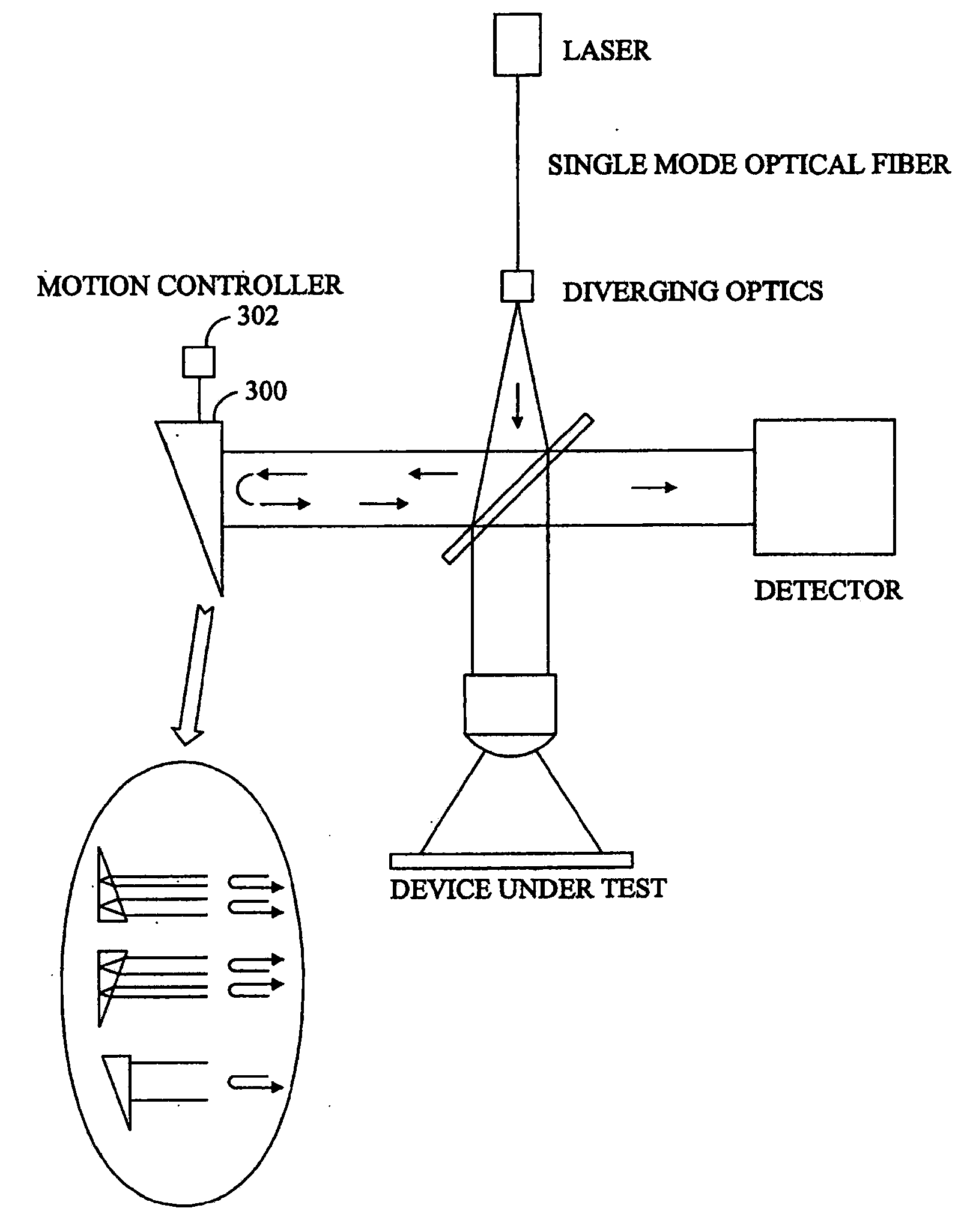
[0020]The present inventors came to the realization that the single point non-invasive probing technique of semiconductor materials could be enhanced if an area significantly greater than a wavelength of the optical test signal could be transmitted through or reflected off of a semiconductor material. Semiconductor materials generally exhibit electro-optic or photo-refractive effects, which can be made to become birefringent by the application of an electric field, either as such or as embodied in electromagnetic radiation. The present inventors then came to the realization that if an object in a state in which it is not birefringent, but such birefringence can then be brought about by electrical or electromagnetic techniques, the nature of the birefringence so introduced can be studied to determine characteristics of the material. Upon further consideration the present inventors then came to the realization that interferometry techniques can sense a wide region, such as that passin...


PUM


Abstract

A method for optically testing semiconductor devices or wafers using a holographic optical interference system with light source providing a light beam of coherent wavelength with a wavelength to which the semiconductor material is transparent, splitting the light beam into a reference beam and an object beam, imposing the object beam on the semiconductor material to generate a reflected object beam reflected from interior structures of the semiconductor material, adjusting the angle of the reference beam relative to the object beam between a plurality of angles with the semiconductor material being a different state for each angle of the reference beam, imposing the reflected object beam and the reference beam onto a detection device to create a plurality of interference patterns, one for each of the reference beam angles, and comparing the interference patterns to one another to determine and display characteristics within the semiconductor material.

Description

CROSS REFERENCE TO RELATED APPLICATION(S)[0001]This application is a continuation of U.S. application Ser. No. 11 / 278,389, filed Mar. 31, 2006, which is a continuation of U.S. application Ser. No. 10 / 301,030, filed Nov. 20, 2002, now U.S. Pat. No. 7,206,078 issued Apr. 17, 2007, which claims the benefit of U.S. Provisional Application No. 60 / 337,419, filed Dec. 6, 2001.BACKGROUND OF THE INVENTION[0002]The present invention relates to non-invasive testing.[0003]The development of advanced integrated circuit devices and architectures has been spurred by the ever increasing need for speed. For example, microwave, fiber optical digital data transmission, high-speed data acquisition, and the constant push for faster digital logic in high speed computers and signal processors has created new demands on high-speed electronic instrumentation for testing purposes.[0004]Conventional test instruments primarily include two features, the integrated circuit probe that connects the test instrument...

Claims


Application Information

Patent Timeline
IPC IPC(8): G01B9/021G01B9/02G01B11/24G01N21/17G01N21/23H01L21/66
CPCG01B11/2441G01N21/1717G01N21/23G01N2021/1721H01L22/12G01N21/17
Inventor PFAFF, PAUL
Owner ATTOFEMTO
Why Eureka
Try Eureka