Thermal Overload Protection

a technology of overload protection and thermal insulation, applied in the direction of emergency protective arrangements responsive to undesired changes, dynamo-electric converter control, motor/generator/converter stoppers, etc., can solve the problems of motor damage, stator coil isolation damage, and difficulty in placing sensors correctly, so as to reduce power consumption, production costs and physical size of the device, the effect of less memory

a technology of overload protection and thermal insulation, applied in the direction of emergency protective arrangements responsive to undesired changes, dynamo-electric converter control, motor/generator/converter stoppers, etc., can solve the problems of motor damage, stator coil isolation damage, and difficulty in placing sensors correctly, so as to reduce power consumption, production costs and physical size of the device, the effect of less memory

US20080253041A1Inactive Publication Date: 2008-10-16ABB OY

Image

  • Thermal Overload Protection
  • Thermal Overload Protection
  • Thermal Overload Protection

Examples


Embodiment Construction

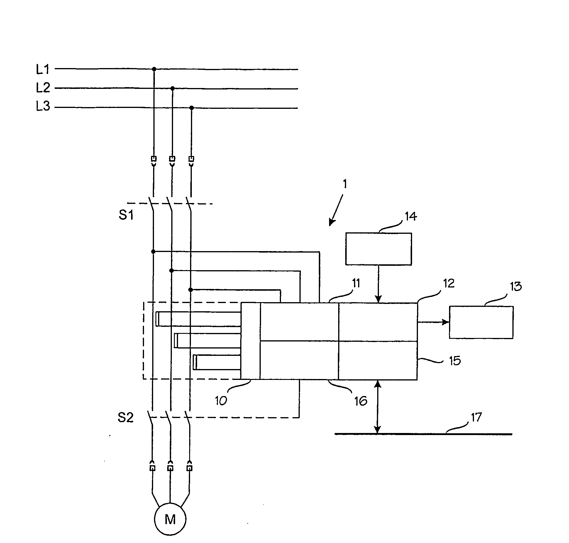
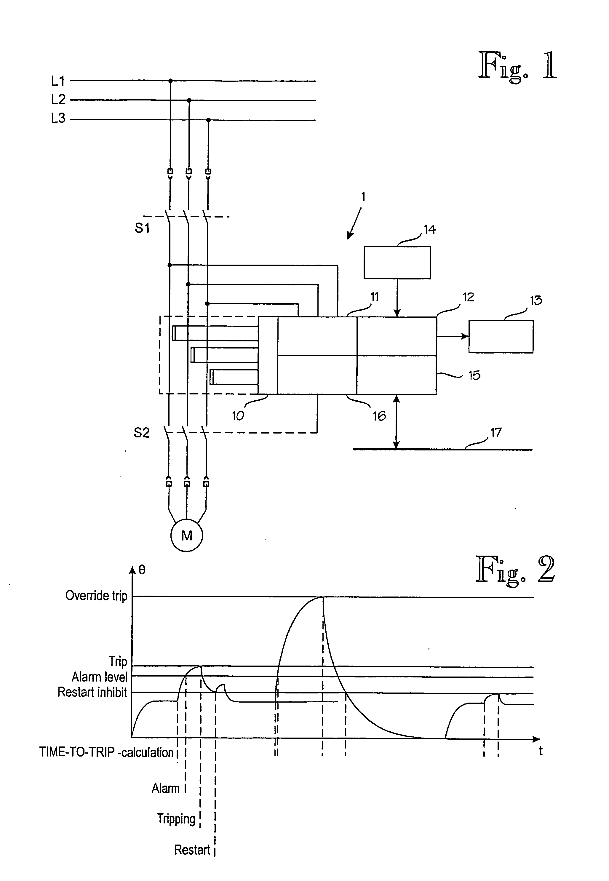
[0022]In FIG. 1, a thermal overload protection is coupled between an electric motor M or other electrical device to be protected and a three-phase mains current supply L1, L2 and L3. S1 is a main mains switch, e.g. manually controlled, and S2 is a release switch controlled by the overload protection and controlled with a trip signal TRIP. The overload protection 1 measures the current load of each phase L1, L2 and L3 of the mains current supply of the motor M with a current measurement unit 10, which is based on current transformers, for example. In addition, the overload protection 1 may comprise a measuring unit 11 for measuring phase voltages. Further, the overload protection 1 preferably comprises a user interface, i.e. a human-machine-interface (HMI) 12, with a display 13 and a keyboard 14. Furthermore, the overload protection 1 may comprise a data communication unit 15 connected to a local area network (e.g. Ethernet), a bus, a field bus (e.g. Profibus DP) or another data comm...


PUM


Abstract

A thermal overload protection for an electrical device, particularly an electric motor (M), measures a load current supplied to the electrical device (M), and calculates the thermal load on the electrical device on the basis of the measured load current, and shuts off (S2) a current supply (L1, L2, L3) when the thermal load reaches a given threshold level. The protection comprises a processor system employing X-bit, preferably X=32, fixed-point arithmetic, wherein the thermal load is calculated by a mathematic equation programmed into the microprocessor system structured such that a result or a provisional result never exceeds the X-bit value.

Description

BACKGROUND OF THE INVENTION[0001]The invention relates to thermal overload protection for protecting electrical devices, and particularly electric motors, from overheating.[0002]Electric motors are utilized in several applications for driving various moving parts. An electric motor often has an associated control unit for adjusting and monitoring the operation of the electric motor, the speed of rotation, for example.[0003]An electric motor may temporarily operate also overloaded, but if it becomes overheated as the loading continues, this may result in damage to the motor. Damage to the isolation of the stator coiling caused by overheating is the most critical.[0004]Various solutions are known for protecting an electric motor against thermal overload. One known solution is based on 1 . . . 3-phase measurement of the motor current and on modelling the heating of the motor by using an RC equivalent circuit. The oldest and most common technical implementation is a bimetallic relay (th...

Claims


Application Information

Patent Timeline
16 Oct 2008
Publication
US20080253041A1
IPC
H02H7/085; H02H6/00
CPC
H02H6/005; H02H7/085
Inventors
KUIVALAINEN, JANNE; OSTERBACK, PETER