Method and apparatus for reference signal generation in wireless communication system

a wireless communication system and reference signal technology, applied in the field of wireless communication systems, can solve the problems of too large difference between the resource and achieve the effect of excellent cross (mutual) correlation property and significant reduction of the difference between the resource block size of the reference signal and the cazac sequence length

Active Publication Date: 2008-10-16
NEC CORP
View PDF10 Cites 74 Cited by
  • Summary
  • Abstract
  • Description
  • Claims
  • Application Information

AI Technical Summary

Benefits of technology

[0087]By generating the reference signal as described, the difference between the resource block size of the reference signal and the CAZAC sequence length can be significantly reduced, compared with the conventional methods, and furthermore, many usable sequences having excellent cross (mutual)-correlation property can be obtained.

Problems solved by technology

As described above, in order to have the greatest number of sequences available, it is optimal to select a prime number as a sequence length of CAZAC sequences, however, when many resource blocks are assigned to one user equipment, the difference between the resource size of the reference signal and the CAZAC sequence length may become too large.
In such a case where the difference between the sequence length of a prime number and the resource size (the sub-carrier number N) of the reference signal is large, the following problems may occur.

Method used


Image

  • Method and apparatus for reference signal generation in wireless communication system
  • Method and apparatus for reference signal generation in wireless communication system
  • Method and apparatus for reference signal generation in wireless communication system

Examples


example 1

8. Wireless Communication System

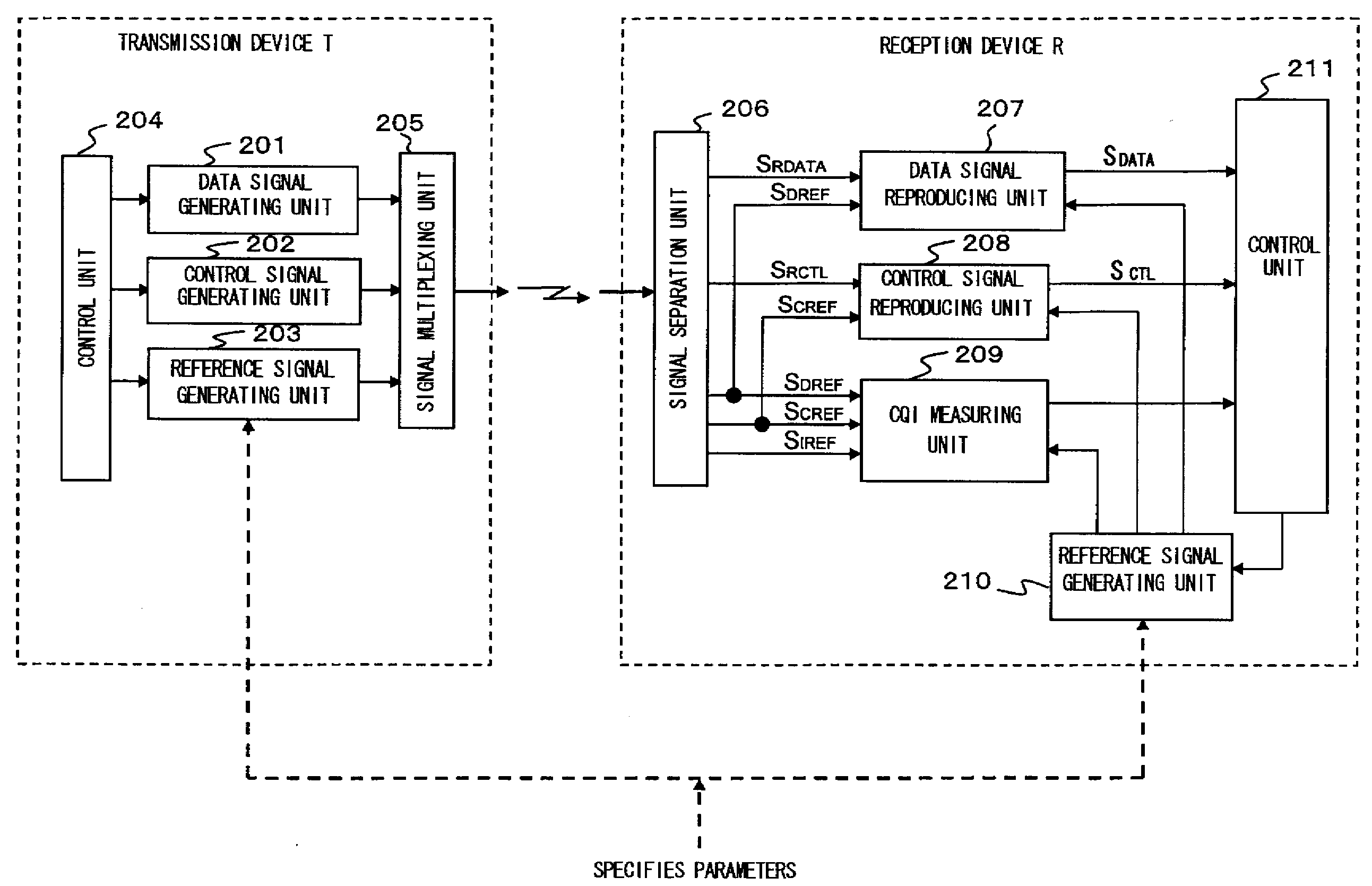
[0172]FIG. 15 is a schematic block diagram of a wireless communication system according to a first example of the present invention. Here, in order to simplify the explanation, only main parts relating to the present invention in a transmission device T and a reception device R are shown in the drawing.

[0173]In order to perform channel estimation using the reference signal, the sequence of the reference signal transmitted between the transmission device T and the reception device R has to be known. In the wireless communication system shown in FIG. 15, reference signal generating units 203 and 210 according to the present example are respectively provided in the transmission device T and the reception device R.

[0174]Further, the reference signal generating units 203 and 210 have the basic configuration shown in FIG. 4, generate CAZAC sequences using the equations (1) and (2) aforementioned according to specified parameters (the sequence length L and t...

example 2

[0180]FIG. 16 is a block diagram showing the main structure of a base station in a wireless communication system according to a second example of the present invention. Here, the base station 30 accommodates a plurality of user equipments (mobile terminals) UE1, UE2 . . . . The base station 30 relating to the present example is mainly constituted by a wireless transmission / reception unit (Tx / Rx) 301, a reception processing unit R, a reference signal generating unit 306, a control unit 307, a resource managing unit 308, and a transmission processing unit T.

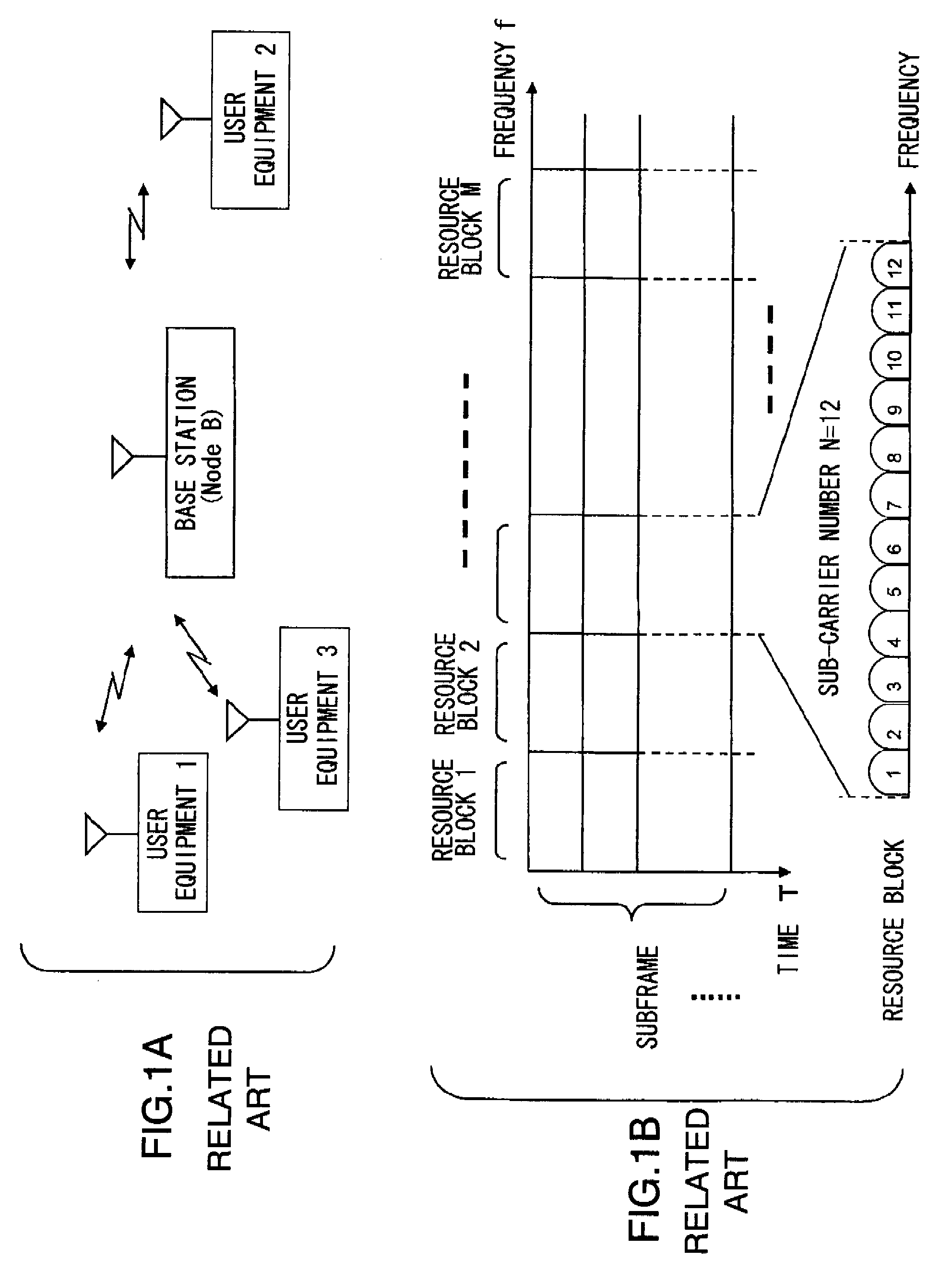
[0181]The wireless transmission / reception unit (Tx / Rx) 301 transmits / receives a wireless signal to / from a plurality of the user equipments UE through each channel having the frequency / time multiplex structure shown in FIG. 1B, for instance. The wireless transmission / reception unit 301 outputs a multiplexed received signal from a plurality of the user equipments UE to the reception processing unit R, converts a multiplexed transmiss...

example 3

[0192]FIG. 17 is a block diagram showing the main structure of a user equipment (mobile terminal of cell phone) in a wireless communication system according to a third example of the present invention. Since the user equipment 40 does not perform resource management, the resources used in transmission / reception are set according to the uplink and downlink resource allocation information received from the base station 30. Further, the user equipment 40 enables the communication with the base station by using the parameters for generating the reference signal notified from the base station 30 to set reference signal generating units 406 and 410. The configuration of the user equipment will be briefly described.

[0193]In FIG. 17, the user equipment 40 relating to the present example comprises, as main components, a wireless transmission / reception unit (Tx / Rx) 401, a reception processing unit R, a reference signal generating unit 406, a control unit 407, and a transmission processing uni...


PUM


Abstract

To provide a reference signal generation method and apparatus capable of obtaining many reference signal sequences having excellent properties. CAZAC sequences that satisfy the condition that the absolute value (|N−L|) of a difference between a sub-carrier number N in a resource block and a CAZAC sequence length L is not larger than a threshold value K are selected, and a sequence having a largest among greatest prime factors among the prime factors constituting the sequence length(s) is further selected from the initially selected sequences. Then, a reference signal sequence(s) is generated from a selected CAZAC sequence.

Description

REFERENCE TO RELATED APPLICATION[0001]This application is based upon and claims the benefit of the priority of Japanese patent application No. 2007-026150, filed on Feb. 5, 2007, the disclosure of which is incorporated herein in its entirety by reference thereto.FIELD OF THE INVENTION[0002]The present invention relates to a wireless communication system, and particularly to a wireless communication system in which a transmission signal and a reference signal (also known as pilot signal) are multiplexed and to a method and apparatus for generating the reference signal.BACKGROUND OF THE INVENTION[0003]The background of the present invention will be explained using a 3GPP wireless communication system shown in FIG. 1 as an example.[0004]FIG. 1A is a block diagram showing a general wireless mobile communication system and FIG. 1B is a format diagram showing an example of a frame structure of a signal transmitted / received between a base station and a mobile terminal, referred to as “user...

Claims


Application Information

Patent Timeline
Patent Type & Authority Applications(United States)
IPC IPC(8): H04L27/06H04Q7/20
CPCH04L27/2613H04L27/26134H04J13/0059
Inventor KAKURA, YOSHIKAZUOKETANI, KENGO
Owner NEC CORP
Why Eureka
Try Eureka