
Balloons Having Improved Strength and Methods for Making Same

a technology of strength and balloons, applied in the field of balloon catheters, can solve the problems of stenosis that requires treatment, threatens the re-closure of the dilated vessel, and polymeric materials have a relatively low yield point, and achieves the effect of high burst strength and same flexibility

Inactive Publication Date: 2008-10-16
MEDTRONIC VASCULAR INC
View PDF7 Cites 11 Cited by
  • Summary
  • Abstract
  • Description
  • Claims
  • Application Information

AI Technical Summary

Benefits of technology

[0014]It is an aspect of the present invention to provide a balloon catheter assembly that includes a balloon that has higher burst strength, and substantially the same flexibility as conventional balloons.
[0016]It is another aspect of the present invention to provide a method for manufacturing a balloon catheter assembly that includes a balloon that has higher burst strength, lower compliance, and substantially the same flexibility as conventional balloons.

Problems solved by technology

Often, however, a stenosis requires treatment with multiple balloon inflations.
Dilation of the occlusion, however, can form flaps, fissures or dissections, which may threaten re-closure of the dilated vessel.
These polymeric materials have a relatively low yield point.
However, since this realignment is permanent, the balloon will not follow its original stress-strain curve on the subsequent inflation-deflation cycles.
Despite the use of high strength engineering polymers, access to highly occluded vessels and lesions in small vessels is still limited.
Many of the balloons that are currently available do not have a proper balance of competing properties.
While balloons made from polyethylene terephthalate (PET) can have lower profiles than other balloons, such as polyamide copolymer balloons, the PET balloon is stiff, has a higher modulus, and therefore has inferior trackability.
While balloons made from polyamide copolymers tend to have better trackability than PET balloons due to their lower modulus, they also have higher profiles, thereby limiting their application.
The flexibility of the balloon may be increased by decreasing the wall thickness of the balloon, but such a decrease may reduce the burst strength of the balloon.
Furthermore, in attempting to produce low profile balloons by wrapping the balloon, the wrapping process often serves to reduce the burst strength of the balloon.

Method used


Image

  • Balloons Having Improved Strength and Methods for Making Same
  • Balloons Having Improved Strength and Methods for Making Same
  • Balloons Having Improved Strength and Methods for Making Same

Examples


Embodiment Construction

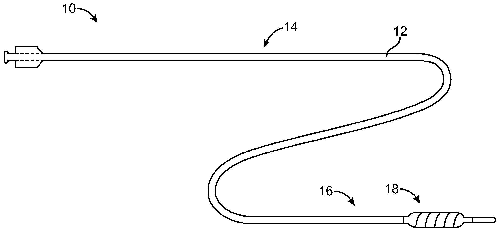
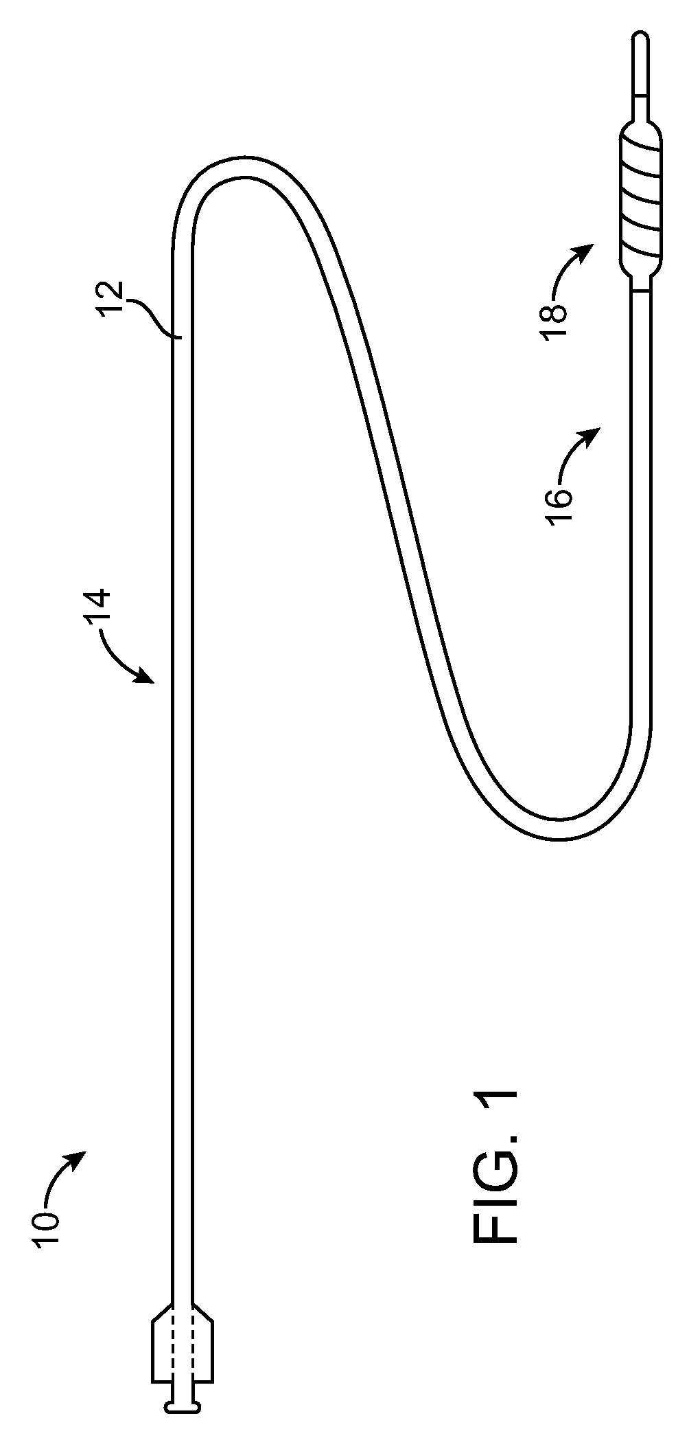
[0027]FIG. 1 illustrates a balloon catheter assembly 10 according to embodiments of the present invention. As illustrated, the assembly 10 includes a catheter shaft 12 having a proximal section 14 and a distal section 16, and a balloon 18 mounted to the distal section 16 of the shaft 12. The shaft 12 may be made from any suitable material, including but not limited to polyamides, polyolefins, and polyesters. The shaft 12 may be formed by any suitable process, such as extrusion or injection molding, as is known in the art.

[0028]According to embodiments of the present invention, the balloon 18 may be used in a wide range of applications for angioplasty, stent delivery and other applications, including, but not limited to cardiovascular, neurovascular and peripheral applications. Although specific examples of balloons for particular applications are described for exemplary purposes, it should be understood that the scope of the invention is not limited to the exemplified balloons. Whil...


PUM


Abstract

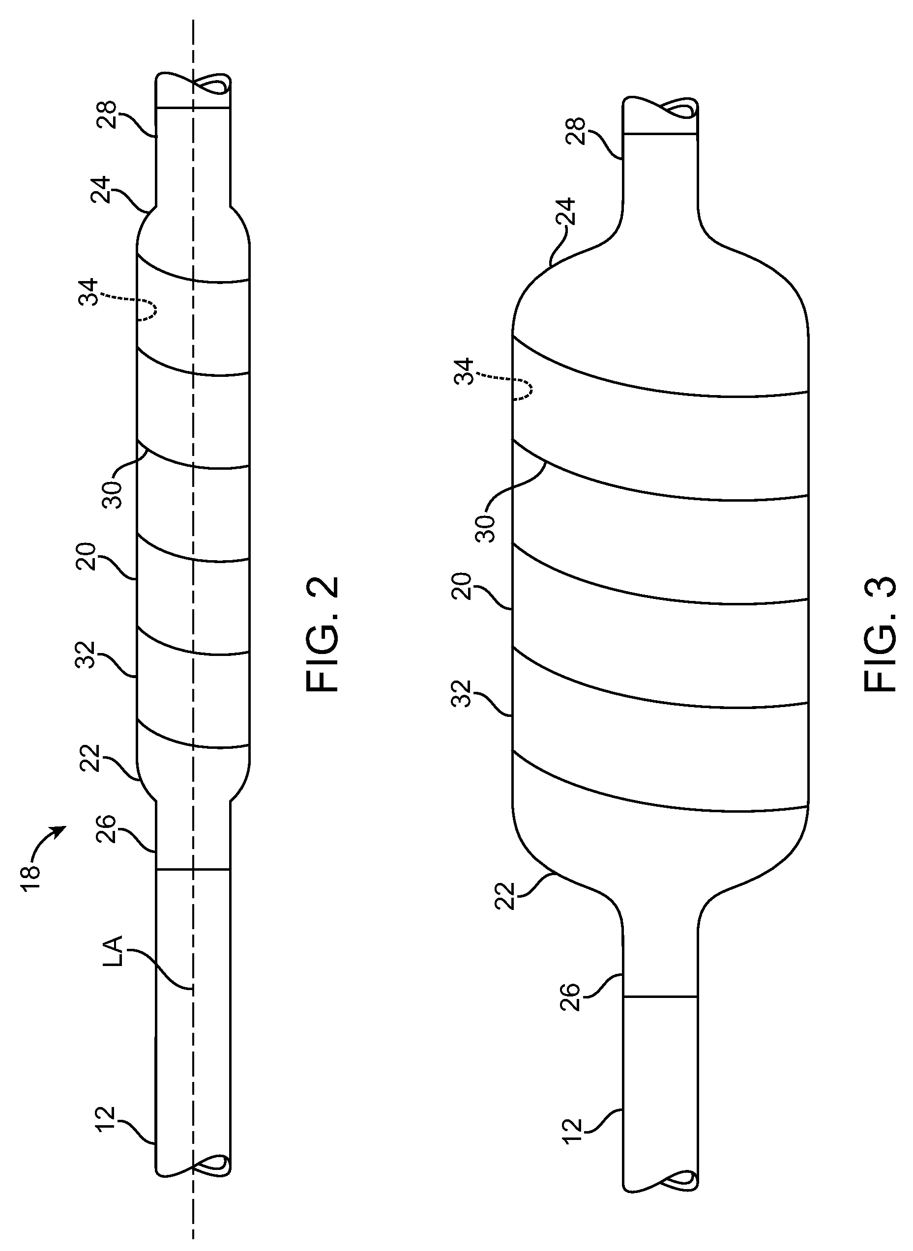
A balloon catheter assembly includes a catheter shaft, and a balloon mounted on the catheter shaft. The balloon includes a distal neck portion, a proximal neck portion, and an inflatable body portion in between the distal and proximal neck portions. The distal and proximal neck portions are connected to the catheter shaft. The balloon also includes a fiber provided on the body portion. The fiber is oriented relative to the longitudinal axis of the body portion at an angle between about 45° and about 135°, and has a diameter of less than about 10 μm.

Description

BACKGROUND OF THE INVENTION[0001]1. Field of the Invention[0002]The present invention generally relates to balloon catheters, and more specifically relates to balloons having improved strength, such as hoop strength, and methods for making such balloons.[0003]2. Description of Related Art[0004]Surgical procedures employing balloons and medical devices incorporating those balloons (i.e. balloon catheters) are becoming more common and routine. These procedures, such as angioplasty procedures, are conducted when it becomes necessary to expand or open narrow or obstructed openings in blood vessels and other passageways in the body to increase the flow through the obstructed areas. For example, in the technique of Percutaneous Transluminal Coronary Angioplasty (PTCA), a dilatation balloon catheter is used to enlarge or open an occluded blood vessel which is partially restricted or obstructed due to the existence of a hardened stenosis or buildup within the vessel. During a PTCA procedure...

Claims


Application Information

Patent Timeline
IPC IPC(8): A61M25/10A61F2/958
CPCA61F2/958A61M25/10A61M25/1027A61M2025/1084
Inventor KRIVORUCHKO, MICHAEL
Owner MEDTRONIC VASCULAR INC
Learn More