Production method of an acoustic diaphragm, acoustic diaphragm, and a speaker

a production method and diaphragm technology, applied in the direction of transducer diaphragms, electromechanical transducers, instruments, etc., can solve the problems of air leakage, sound deterioration, sound deterioration, etc., to reduce the viscosity, increase permeability, and slow the hardening

Inactive Publication Date: 2008-10-23
VICTOR CO OF JAPAN LTD
View PDF0 Cites 2 Cited by
  • Summary
  • Abstract
  • Description
  • Claims
  • Application Information

AI Technical Summary

Benefits of technology

[0012]An object of the present invention is to cover the fine holes of a diaphragm having a high carbonization ratio which are generated in a process of burning a natural diaphragm material containing various types of organic matter and to prevent sound deterioration due to air leakage when the diaphragm is used in a speaker.
[0013]Another object of the present invention is to realize an improvement in the strength of the acoustic diaphragm having a high carbonization ratio and to improve the manageability in an assembling process of a speaker using the diaphragm and to improve the strength reliability of the speaker.
[0014]Another object of the present invention is to increase internal losses of an acoustic diaphragm and to absorb strain components of the diaphragm used in a speaker, in order to improve frequency characteristic.

Problems solved by technology

As a result, air leakage occurs when such a diaphragm is used as a speaker.
The air leakage causes sound deterioration, which is a problem to be solved for an acoustic diaphragm used in a speaker.
The other compression air wave creates noise and the noise causes sound deterioration.
However, JP 60-54596 does not disclose a feature for air leakage.
Also, it is not clear whether or not the thin metal layer can prevent the air leakage.
However, it is not still clear that the above thin metal layer can prevent the air leakage.
However, JP 57-31356 does not disclose the feature for air leakage and it is not clear whether or not the thin metal layer prevents the air leakage.
However, JP 2002-34096 does not disclose a feature for preventing air leakage and it is not clear whether or not the impregnated burned porous surface prevents the air leakage.
Any effective feature for an air leakage is not taken or is not sufficient.

Method used


Image

  • Production method of an acoustic diaphragm, acoustic diaphragm, and a speaker
  • Production method of an acoustic diaphragm, acoustic diaphragm, and a speaker
  • Production method of an acoustic diaphragm, acoustic diaphragm, and a speaker

Examples


first embodiment

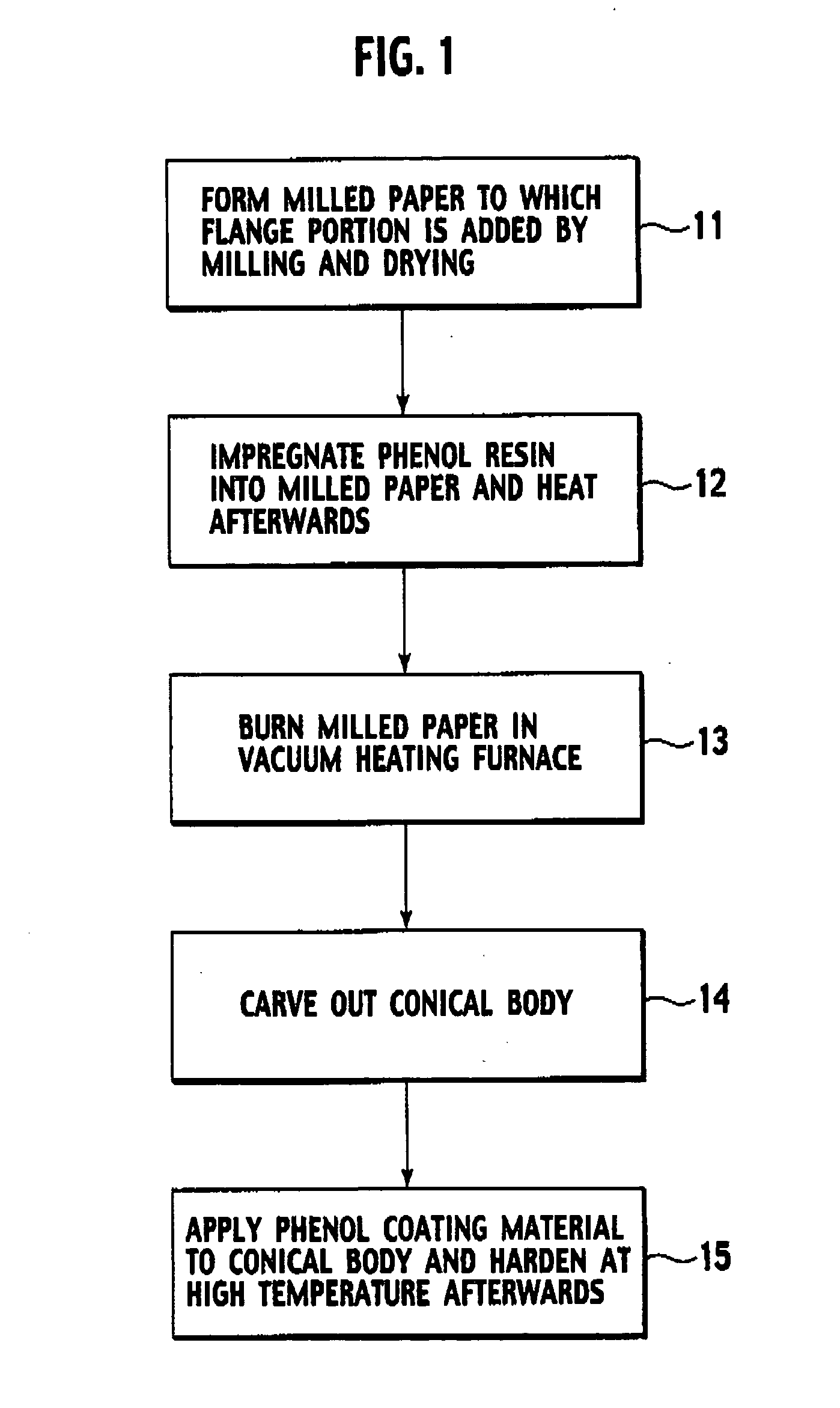
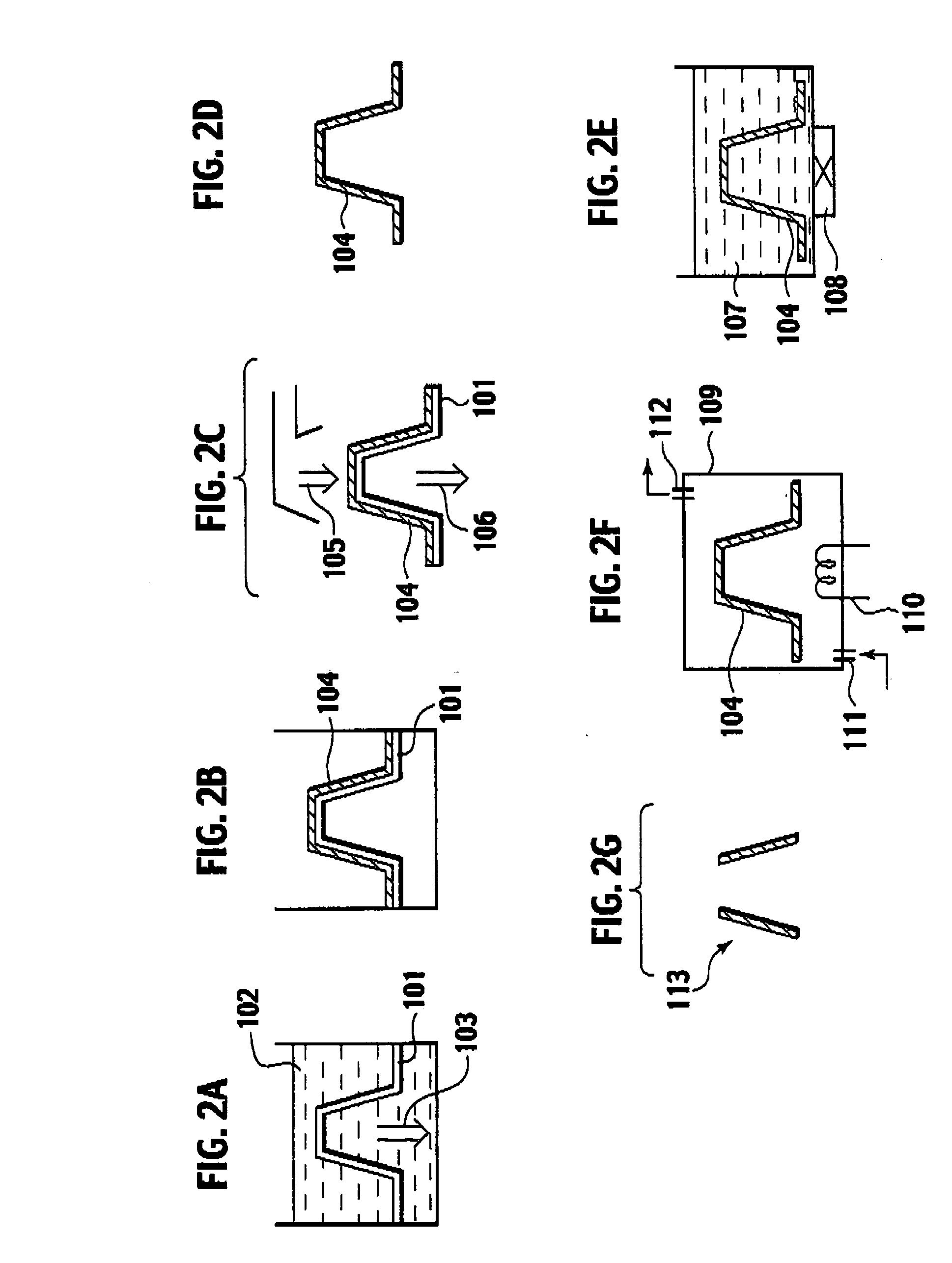
[0071]A first embodiment of the present invention will be described. FIGS. 1 and 2A to 2F are explanatory diagrams of a production method according to the first embodiment.

[0072]At a first step 11 in FIG. 1, as shown in FIG. 2A, a previously formed mesh 101 having a center portion has a conical shape (truncated shape) is prepared. (Since the workpiece contracts due to a burning operation, the mesh may be formed larger than the size of the workpiece after the burning operation. For example, when it is heated at 800° C., contraction of, for example, 25% in the longitudinal direction is taken into consideration, and the mesh is formed larger by this value.) The mesh 101 is put into a dispersion liquid 102 into which mixture fiber of 90 wt % of linter (cotton fiber) 10 wt %+NBKP [Needle Bleach Kraft Pulp] (softwood fiber is made into pulp by the kraft process and is further bleached) is dispersed, and the mixture fiber is milled into paper on the mesh 101. A reference number 103 in FIG....

second embodiment

[0083]FIGS. 4 and 5A to 5G are explanatory diagrams of a production method according to the second embodiment.

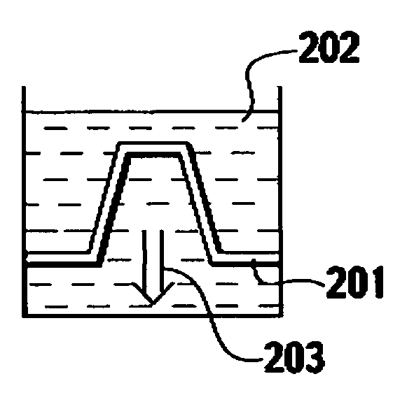
[0084]At a first step 21 in FIG. 4, as shown in FIG. 5A, a previously formed mesh 201 having a center portion has a conical shape (truncated shape) is prepared. (Since the workpiece contracts due to a burning operation, the mesh may be formed larger than the size of the workpiece after the burning operation. For example, when it is heated at 800° C., contraction of, for example, 25% in the longitudinal direction is taken into consideration, and the mesh is formed larger by this value). The mesh 201 is put into a dispersion liquid 202 into which mixture fiber of 90 wt % of linter (cotton fiber) 10 wt %+NBKP [Needle Bleach Kraft Pulp] (softwood fiber is made into pulp by a kraft process and is further bleached) is dispersed, and the mixture fiber is milled into paper on the mesh 201.

[0085]A reference number 203 represents a suction direction when paper is milled, and a referen...

third embodiment

[0097]FIGS. 6 and 7A to 7H are explanatory diagrams of a production method according to a third embodiment.

[0098]At a first step 31 in FIG. 6, as shown in FIG. 7A, a previously formed mesh 301 having a center portion into a domical shape (hemispherical shape) is prepared. (Since the workpiece contracts due to a burning operation, the mesh may be formed larger than the size of the workpiece after the burning operation. For example, when the it is heated at 800° C., contraction of, for example, 25% in the longitudinal direction is taken into consideration, and the mesh may be formed larger by this value). The mesh 301 is put into dispersion liquid 302 into which mixture fiber of 90 wt % of linter (cotton fiber) 10 wt %+NEKP [Needle Bleach Kraft Pulp] (softwood fiber is made into pulp by kraft process and is further bleached) is dispersed, and the mixture fiber is milled into paper on the mesh 301. A reference number 303 represents a suction direction when paper is milled, and a refere...


PUM


Abstract

A method of producing an acoustic diaphragm includes forming a workpiece having a shape of the acoustic diaphragm by using a natural material which can be carbonized by burning; forming a first film including phenol resin on a surface and an interior of the workpiece; heating the workpiece to bring the phenol resin into a high polymer state; burning the workpiece in a substantially anoxic atmosphere to carbonize the workpiece and the first film; and forming a second film including gelatin on at least one of a surface and an interior of carbonized workpiece.

Description

CROSS REFERENCE TO RELATED APPLICATIONS[0001]This application is a continuation-in-part of application Ser. No. 11 / 698,167, filed on Jan. 26, 2007. This application is also based upon and claims the benefit of priority from the prior Japanese Patent Applications No. P2006-019101, filed on Jan. 27, 2006, No. P2006-019105, filed on Jan. 27, 2007, No. P2006-282464, filed on Oct. 17, 2006, No. P2006-282466, filed on Oct. 17, 2006, No. P2007-096873, filed on Apr. 2, 2007, No. P2007-212222, filed on Aug. 16, 2007, and No. P2008-021907, filed Jan. 31, 2008; the entire contents of which are incorporated herein by reference.BACKGROUND OF THE INVENTION[0002]1. Field of the Invention[0003]The present invention relates to a method of producing an acoustic diaphragm, an acoustic diaphragm, and a speaker using the acoustic diaphragm.[0004]2. Description of the Related Art[0005]As an acoustic diaphragm for a speaker that emits a clear sound with minimum distortion, a diaphragm having a high carbon...

Claims


Application Information

Patent Timeline
Patent Type & Authority Applications(United States)
IPC IPC(8): H04R7/02B05D3/02
CPCH04R7/125H04R27/00H04R31/003H04R31/006H04R2307/025H04R2307/029
Inventor SUZUKI, YOSHIAKITANAKA, YOSHIAKIHIROSE, SHINICHI
Owner VICTOR CO OF JAPAN LTD
Why Eureka
Try Eureka