Devices, Systems, and Methods for Carbonation of Deionized Water

a technology of deionized water and carbonation method, which is applied in the direction of isotope separation, electrolysis, water/sewage treatment by substance addition, etc., can solve the problems of toxicity and disposal problems with respect to unused gases, high cost, and large instrumentation complexity, and achieve high surface area, eliminate pockets of higher or lower acidity, and high accuracy the effect of co2 concentration control

Active Publication Date: 2008-10-23
MKS INSTR INC
View PDF11 Cites 27 Cited by
  • Summary
  • Abstract
  • Description
  • Claims
  • Application Information

AI Technical Summary

Benefits of technology

[0016]One advantage of the present invention is the generation of “bubble free” DI-CO2 water. The contactor can provide a high surface area for thorough mixing of the CO2 gas with the DI water such that no excess carbon dioxide remains undissolved. This prevents the formation of bubbles in the DI-CO2 water. “Bubble free” DI water is advantageous for use in wet cleaning applications of semiconductor devices because it eliminates pockets of higher or lower acidity typically caused by bubbles. The “Bubble free” DI-CO2 water generated causes minimum damage to the devices being cleaned.
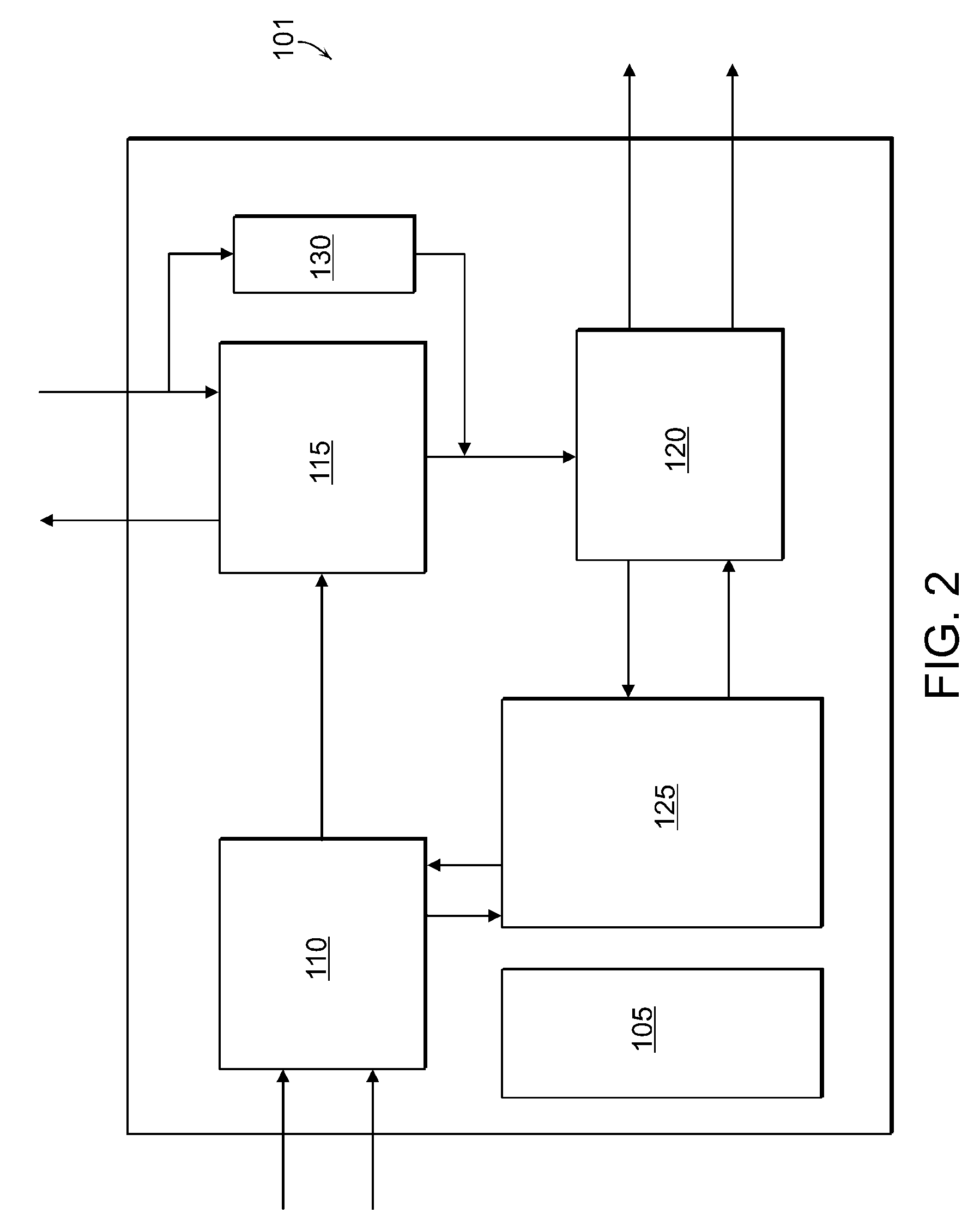
[0017]The conductivity of the DI-CO2 water is proportional to the concentration of the dissolved CO2 gas in the DI water. An advantage of the present invention is that it provides DI-CO2 water with a highly accurate CO2 concentration control. This is typically obtained due to the feed-forward loop mechanism in the system. The feed-forward loop mechanism can co-ordinate the parameters such as conductivity, temperature and flow rate of the DI-CO2 water exiting the contactor with the amount of carbon dioxide gas entering the contactor. The mass flow controllers and the feedback loop mechanism can provide additional control over the conductivity of the DI-CO2 water exiting the contactor. The feedback and feed-forward loop mechanisms also result in significantly reduced response times when the concentration of carbon dioxide in the DI

Problems solved by technology

Controlling the proportions of these gases require considerably complex instrumentation and high costs which are significant disadvantages of current methods.
Typically, an excess of

Method used


Image

  • Devices, Systems, and Methods for Carbonation of Deionized Water
  • Devices, Systems, and Methods for Carbonation of Deionized Water
  • Devices, Systems, and Methods for Carbonation of Deionized Water

Examples


Embodiment Construction

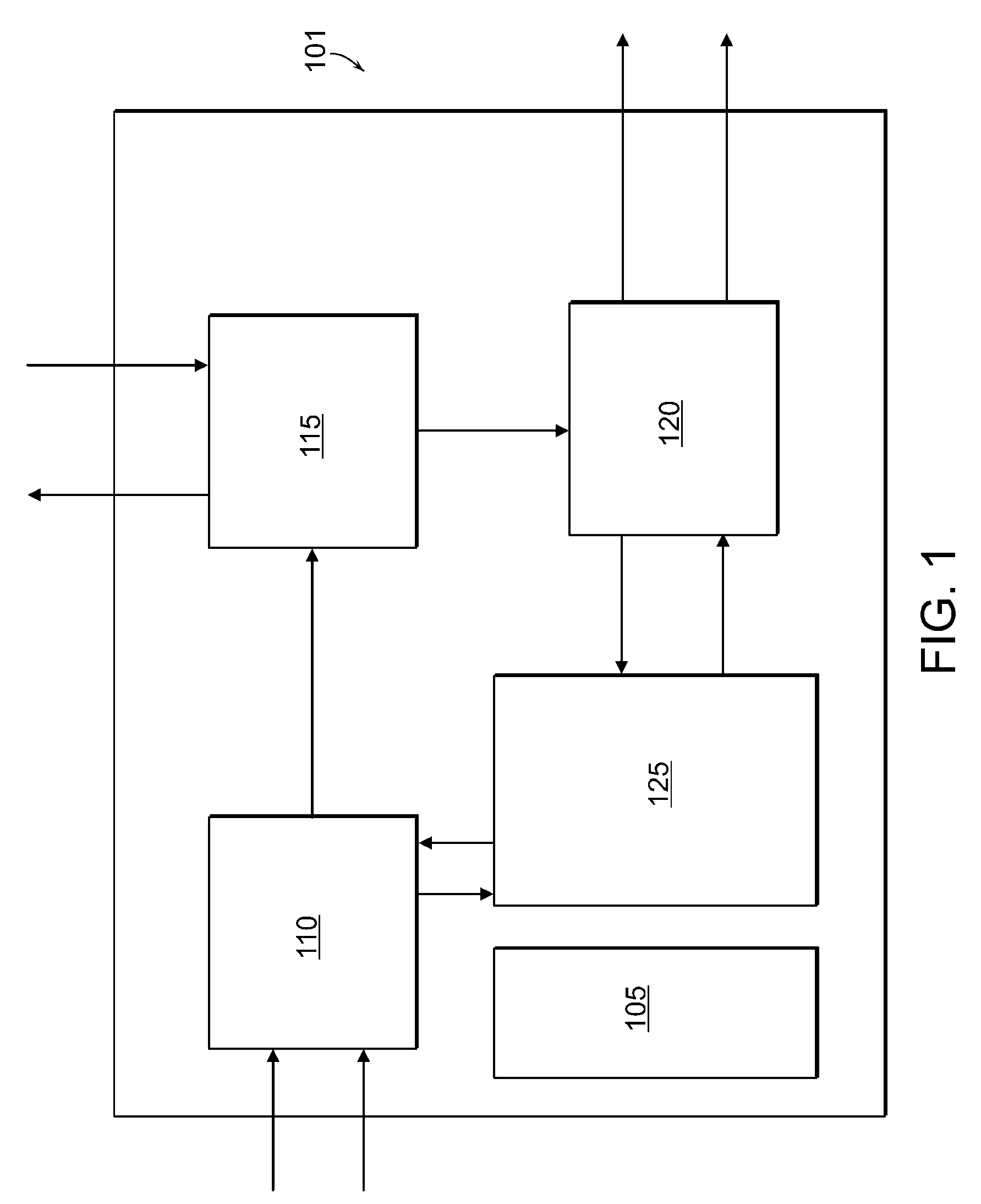
[0032]The present invention provides devices, systems, and methods of making DI-CO2 water for wet cleaning of semiconductor devices. In general, the devices, systems, and methods provide wet cleaning of semiconductor devices while preventing or reducing damage created by electrostatic charge. In one aspect, the invention provides a device with a high level of control and consistency over a desired concentration of carbon dioxide in the DI-CO2 water. In another aspect, the devices, systems and methods can be used to generate DI-CO2 water containing a large range of different CO2 concentrations. For example, the devices, systems and methods can generate low CO2 concentration DI-CO2 water (0.154 mg / L CO2) as well as high CO2 concentration DI-CO2 water (1540 mg / L). In general, the devices, systems, and methods of the present invention eliminate a need for adding excess CO2 gas, nitrogen gas, or any other gas to a contactor for the DI-CO2 generation, thereby reducing the cost, size and c...


PUM

PropertyMeasurementUnit
Electrical conductivityaaaaaaaaaa
Temperatureaaaaaaaaaa
Timeaaaaaaaaaa

Abstract

Devices, systems, and methods employed in wet cleaning semiconductor devices are provided. In particular, systems that can deliver deionized water with the desired concentration of CO2 and methods of generating deionized water with a desired concentration of CO2 for use in wet cleaning of semiconductor devices are provided.

Description

CROSS-REFERENCE TO RELATED APPLICATIONS[0001]This application claims the benefits of and priority to U.S. provisional patent application Ser. No. 60 / 852,265 filed on Oct. 17, 2006, the entire disclosure of which is herein incorporated by reference.FIELD OF THE INVENTION[0002]In general, the invention relates to devices, systems, and methods employed in wet cleaning semiconductor devices. In particular, the invention relates to systems that can deliver deionized water with the desired concentration of CO2 and methods of generating deionized water with a desired concentration of CO2 for use in wet cleaning of semiconductor devices.BACKGROUND OF THE INVENTION[0003]Microelectronics chips such as integrated circuits are made from comparatively large wafers of semiconductor material. This process typically involves multiple successive steps including the following: generation of an etch mask photolithographically; etching of a layer of material as defined by the mask; removal of the photo...

Claims


Application Information

Patent Timeline
IPC IPC(8): B05B7/02C10J1/12
CPCC02F1/685Y10S261/07C02F1/72C02F1/68B01F21/00B01F23/20
Inventor SEIWERT, JOHANNESBRAMMER, ULRICHGOTTSCHALK, CHRISTIANELOHR, JOACHIM
Owner MKS INSTR INC
Why Eureka
Try Eureka