Aircraft kinetic landing energy conversion system

a technology of kinetic landing and conversion system, which is applied in the direction of aircraft braking arrangement, personal actuation, and ways, etc., can solve problems such as drag for

Active Publication Date: 2008-10-23
THE BOEING CO
View PDF22 Cites 77 Cited by
  • Summary
  • Abstract
  • Description
  • Claims
  • Application Information

AI Technical Summary

Benefits of technology

[0019]The induction discharge between the discharge shoe and the receiving conductive elements creates additional braking energy by creating magnetic flux vortices between the discharge shoe coils and runways conduction system. These flux vortices which are formed by the forward motion of the discharge shoe over the runways conductive pick up elements result in a drag force that augments the braking force of the dynamic motor / brake, and also places a load on the generator for conversion of the rotational energy of the wheel to the electrical energy being creating braking regeneration field drag inside the motor / generator.
[0025]There is a thermal separation boundary between the convention brake system and the motor / generator dynamic braking system. This thermal boundary thermally protects the motor / generator from the heat produced by the conventional brakes if they are required to be employed on a rejected take off situation.

Problems solved by technology

These flux vortices which are formed by the forward motion of the discharge shoe over the runways conductive pick up elements result in a drag force that augments the braking force of the dynamic motor / brake, and also places a load on the generator for conversion of the rotational energy of the wheel to the electrical energy being creating braking regeneration field drag inside the motor / generator.

Method used


Image

  • Aircraft kinetic landing energy conversion system
  • Aircraft kinetic landing energy conversion system
  • Aircraft kinetic landing energy conversion system

Examples


Embodiment Construction

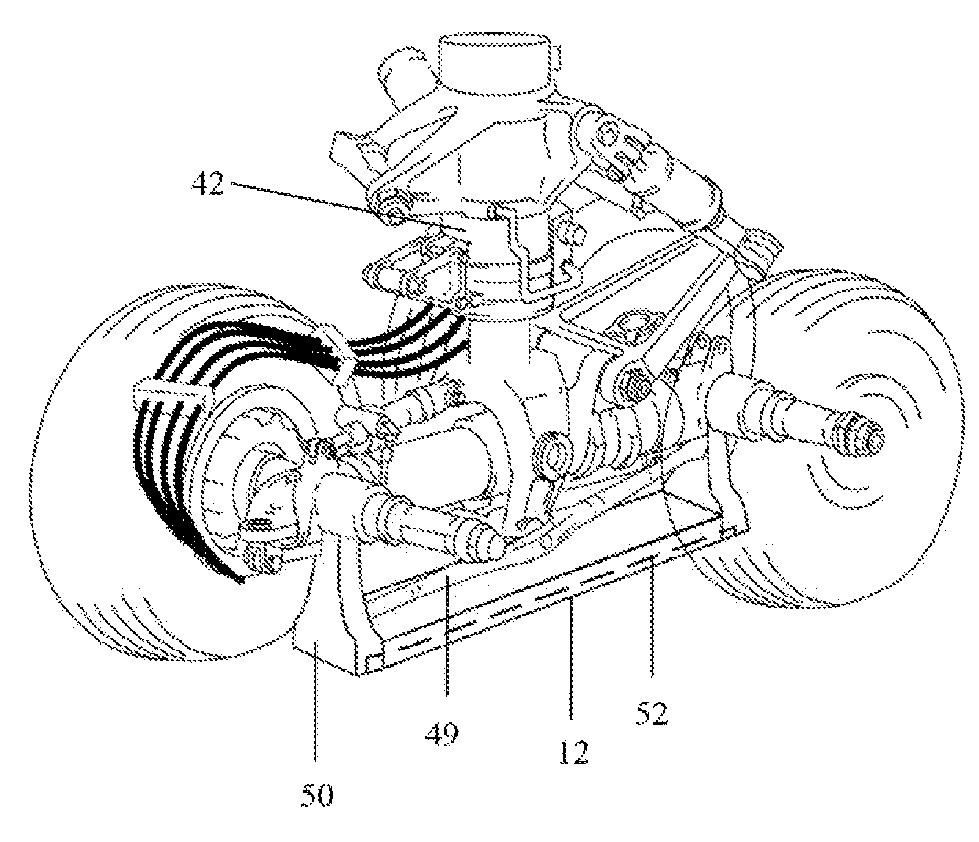
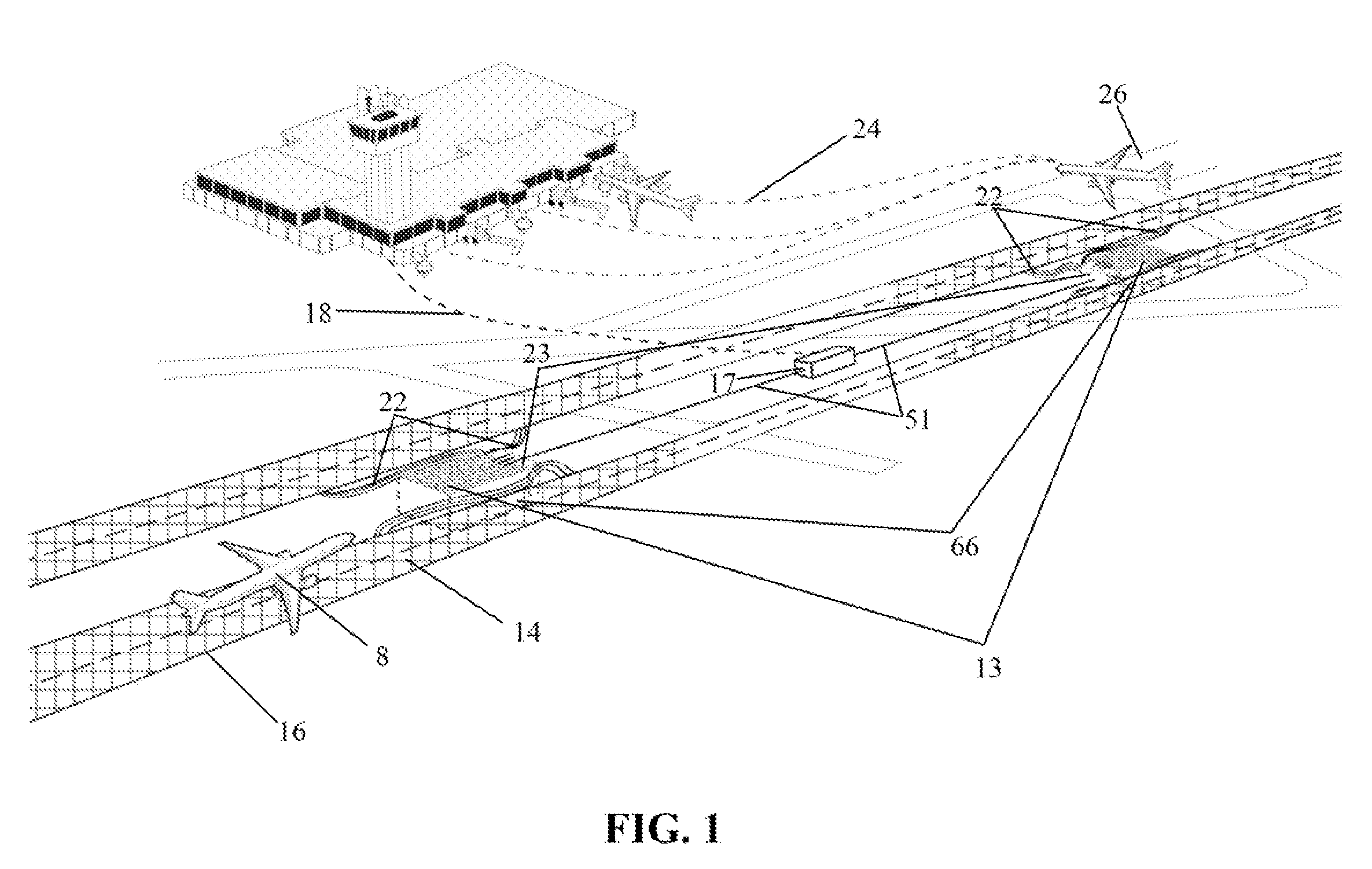
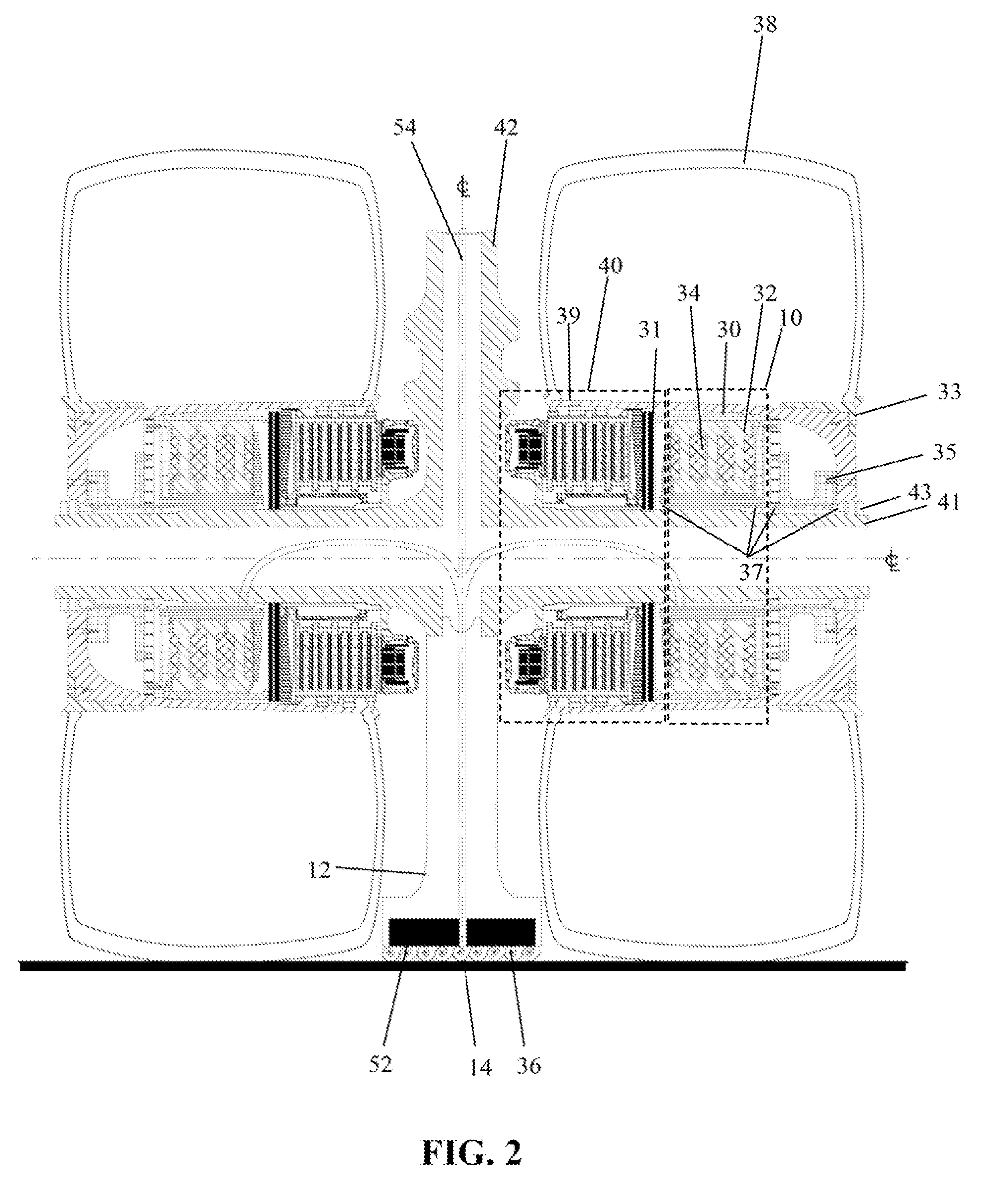
[0033]A system provided by embodiments of the present invention as shown in pictorial form in FIG. 1 with details of the wheel mounted system elements in FIG. 2, makes the aircraft braking system capable of dissipating the majority of the kinetic landing energy from an aircraft in the form of electricity. This discharge of energy is accomplished by the combination of dynamic motor / generator braking, reverse polarity motor / generator energizing in a wheel mounted motor / generator system 10 (seen in FIG. 2) and the off-loaded electrical energy recovered and reformed from the kinetic energy of landing deceleration of an aircraft 8 by means of induction through a transfer shoe 12 discharging into a pick up grid or conductive runway surface material 14 imbedded into or placed onto the runway 16. The pick up grid or conductive surface material in turn transmits the converted landing deceleration energy to one or more dispersal or recovery and storage facilities 20 at a location remote from ...


PUM


Abstract

A kinetic energy system which transfers the kinetic landing into recoverable electric energy for an aircraft. The system incorporates at least one wheel supporting the aircraft for landing and takeoff coupled with a dynamic functioning motor / generator mounted to and operated by rotation of the wheel to create electrical energy from kinetic energy. An induction shoe structurally connected to the aircraft and electrically connected to the motor / generator, which shoe draws the converted energy from the generator which supplies the load created by the inductively coupled induction shoe to the an ancillary load provided by the resistive heat sink on by the capacitor storage bank. This provides the generator circuit for conversion of the rotational energy of the wheel to electrical energy and creates braking drag. In exemplary embodiments, the system employs an energy storage system acting as the load to store electrical potential energy created by the generator. Additionally, the generator is employable as a motor, receiving energy from the storage system for traction power to the associated aircraft wheel. An induction grid or a surface mounted conductive layer mounted into or onto a runway is employed for transferring energy to and from the motor / generator.

Description

[0001]REFERENCE TO RELATED APPLICATIONS[0002]This application claims priority of U.S. provisional application Ser. No. 60 / 872,443 which is a provisional conversion of U.S. application Ser. No. 11 / 738,407 filed on Apr. 20, 2005 having the same title as the present application and a common assignee the disclosure of which is incorporated herein.BACKGROUND OF THE INVENTION[0003]1. Field of the Invention[0004]This invention relates generally to the field of aircraft braking systems and more specifically to a method and system for recovery, storage, and use of kinetic braking energy using wheel-mounted motor / generators to transform kinetic stopping energy into electric energy for transfer through an inductive coupling to an energy recovery and storage system.[0005]2. Description of the Related Art[0006]The main requirement of aircraft braking systems is to be capable of stopping the aircraft at its end of flight destination and is typically used on the order of only a few seconds within ...

Claims


Application Information

Patent Timeline
Patent Type & Authority Applications(United States)
IPC IPC(8): B64C25/42E01C11/00B64C13/00
CPCB60L7/10B60L11/182B64C25/36B64C25/405B60L2200/26Y02T10/7005Y02T50/823Y02T90/122Y02T90/14B64C25/42Y02T10/7072B60L53/12Y02T10/70Y02T50/80Y02T90/12
Inventor MCCOSKEY, WILLIAM R.VANDER WEL, MICHAEL M.JOHNSON, RICHARD N.
Owner THE BOEING CO
Why Eureka
Try Eureka