
Leader Tape and Magnetic Tape Cartridge Using the Same

Inactive Publication Date: 2008-10-23
FUJIFILM CORP
View PDF30 Cites 5 Cited by
  • Summary
  • Abstract
  • Description
  • Claims
  • Application Information

AI Technical Summary

Benefits of technology

[0019]In a leader tape of the present invention, a specific surface roughness is provided, so that a proper gap can be formed between a tape and a tape on winding the tape, as a result, the pressure can be relaxed and a leader block or the like can be prevented from being imprinted on a magnetic tape. Furthermore, the friction coefficient is specified, so that the reduction in the output can be prevented without damaging the recording head even when loading / unloading is repeated.

Problems solved by technology

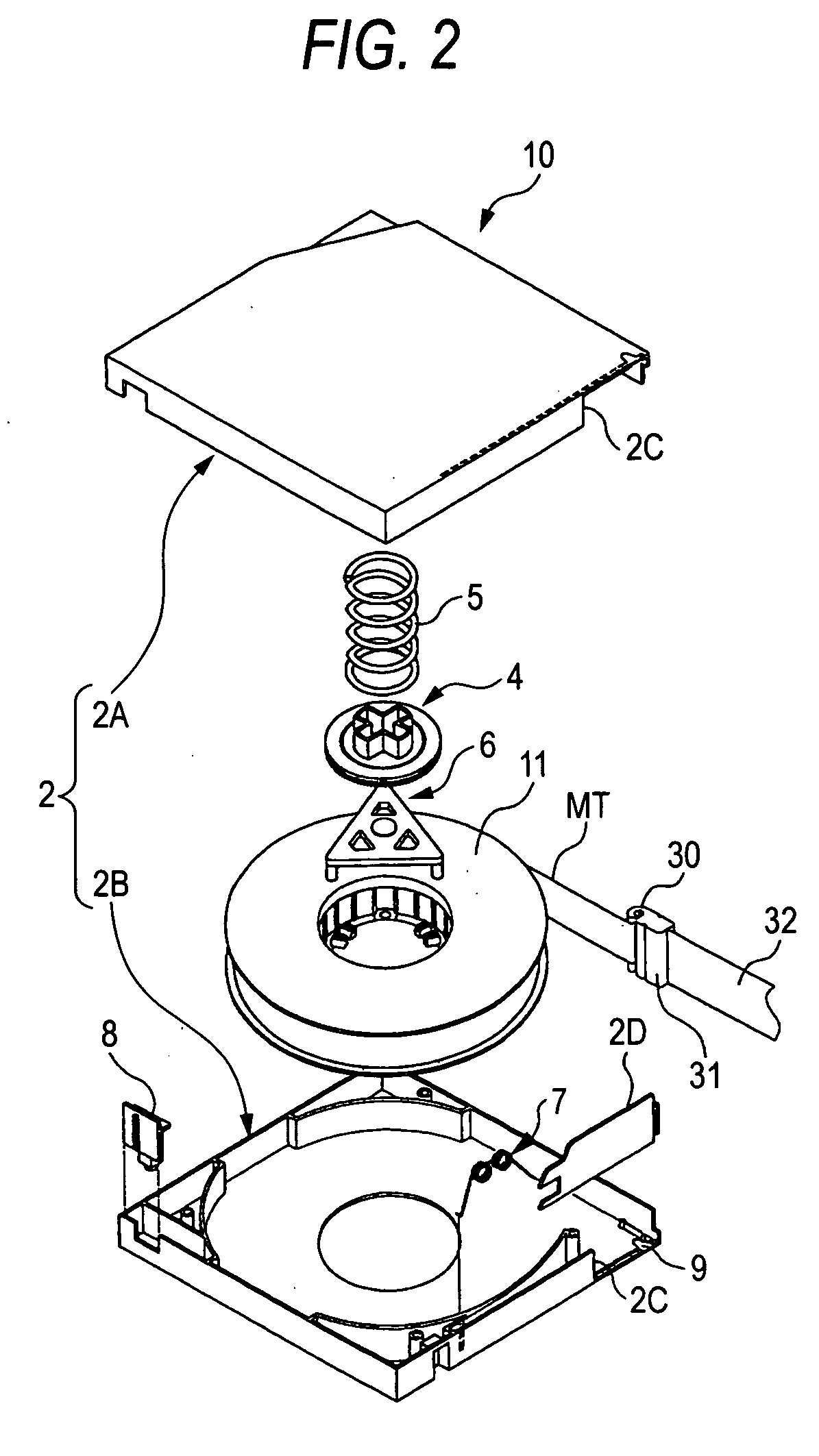
At the time of performing loading / unloading by drawing out the above-described magnetic tape to the magnetic recording and reproducing apparatus side and winding the leading end part around a drive reel in the apparatus, the leading end portion is readily damaged because this portion comes into contact with and is pulled by a tape guide, a magnetic head or the like arranged in the running path while not being correctly positioned.
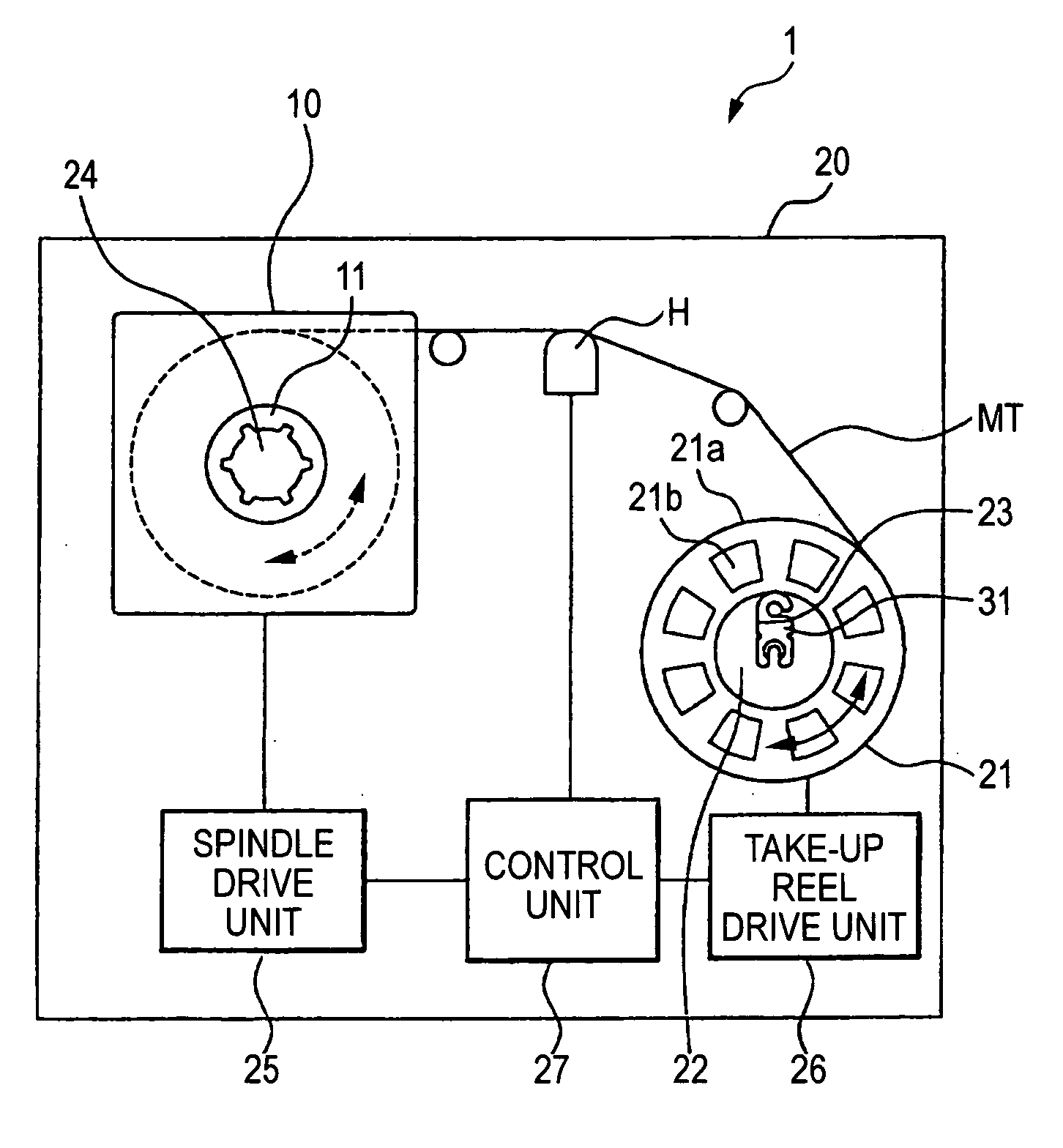
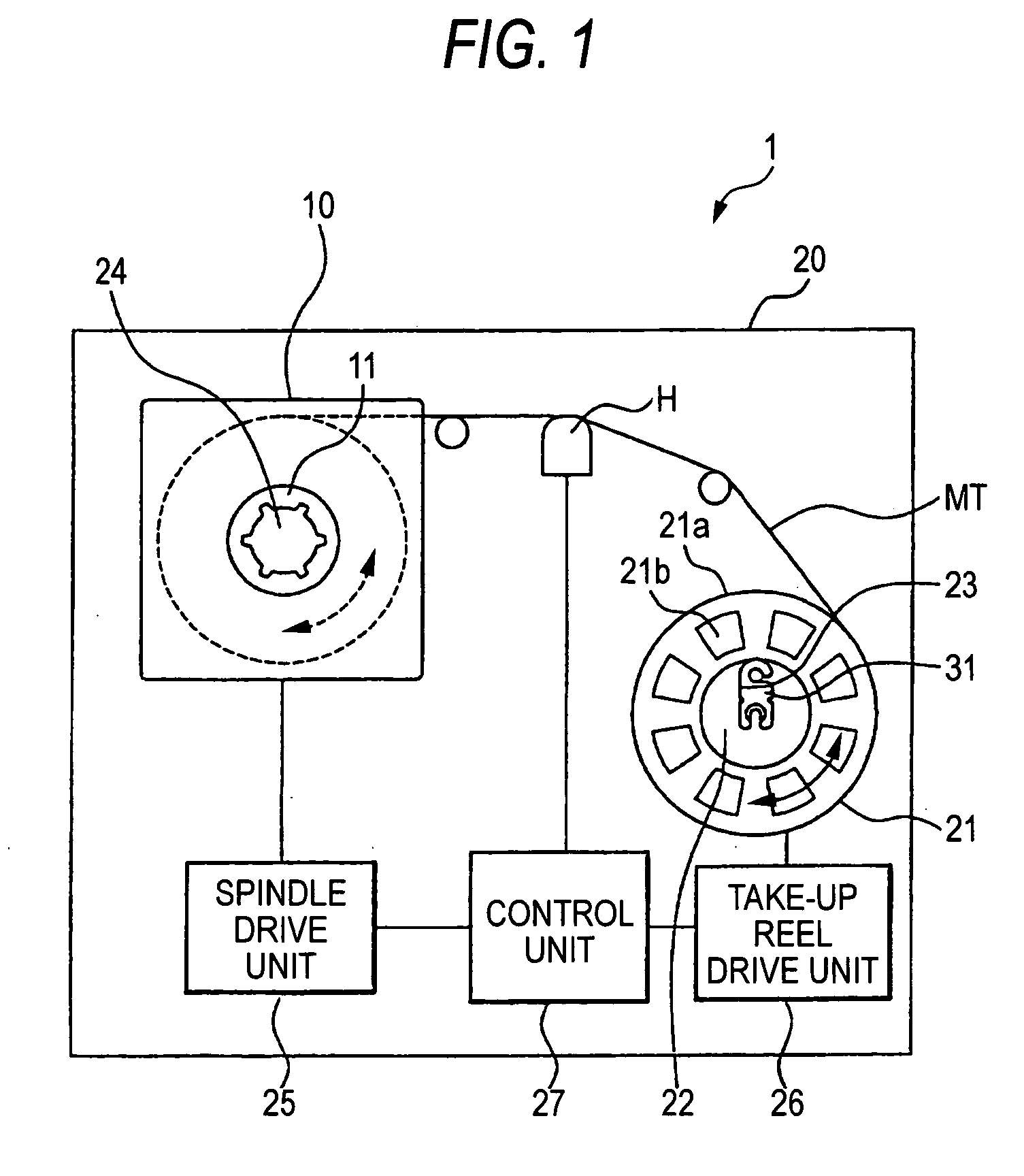
However, in such an existing tape drive, as shown in FIG. 4(b), the end face 40a may protrude from the core part 41 depending on the dimensional accuracy of the leader block 40 constituting a part of the take-up face, and this may bring about an unacceptable level difference on the take-up face of the core part 41.
This tape imprinting readily causes a trouble such as incapability of maintaining an appropriate distance to the recording and reproducing head in the process of recording or reproducing information and gives rise to recording failure or information loss.

Method used


Image

  • Leader Tape and Magnetic Tape Cartridge Using the Same
  • Leader Tape and Magnetic Tape Cartridge Using the Same
  • Leader Tape and Magnetic Tape Cartridge Using the Same

Examples


example 1

[0111]In Examples, the “parts” means “parts by mass”.

Production of Leader Tape:

[0112]

Composition of Coating Material for Upper Layer:Ferromagnetic metal powder100partscoercive force Hc: 128 kA / m (1,600 Oe)specific surface area by BET method: 53 m2 / gcrystallite size: 160 Åsaturation magnetization σs: 130 A·m.2 / kgaverage long axis length: 130 nmaverage acicular ratio: 6.5pH: 9.3Co / Fe: 5 atm %Al / Fe: 7 atm %Y / Fe: 2 atm %water-soluble Na: 5 ppmwater-soluble Ca: 1 ppmwater-soluble Fe: 1 ppmVinyl chloride copolymer (MR-110, produced by10partsZEON Corporation) (—SO3Na content: 5 × 10⁻⁶ eq / g,polymerization degree: 350, epoxy group (3.5 mass %as monomer unit))Polyester polyurethane resin (neopentyl2.5partsglycol / caprolactone polyol / MDI = 0.9 / 2.6 / 1 (bymass), —SO3Na group content: 1 × 10⁻⁴ eq / g)σ-Alumina (average particle diameter: 0.3 μm)10partsCarbon black (average particle diameter: 0.10 μm)1partButyl stearate1.5partsStearic acid0.5partsMethyl ethyl ketone150partsCyclohexanone50partsToluene4...

example 2

[0121]A magnetic tape cartridge of the present invention was prepared in the same manner as in Example 1 except that in the production of the leader tape, a PET support having a center line average surface roughness Ra of 20 nm on both surfaces was used.

example 3

[0122]A magnetic tape cartridge of the present invention was prepared in the same manner as in Example 1 except that in the production of the leader tape, a PET support having a center line average surface roughness Ra of 50 nm on both surfaces was used.


PUM


Abstract

An object is to provide a leader tape which suppresses the increase of dropout resulting from imprinting of the drive reel or leader block part due to storage for a long time or running at a high temperature and hardly causes the edge damage of a magnetic tape, and also provide a magnetic tape cartridge using the leader tape.1) A leader tape comprising a support having provided on at least one surface thereof a coating layer comprising a powder material and a binder, wherein the center line average roughness (Ra) on at least one surface of the leader tape is from 10 to 60 nm and the friction coefficient against an Al2O3 / TiC member is from 0.1 to 0.3; and 2) a magnetic tape cartridge including a cartridge case; and a single reel or a plurality of reels, each reel being rotatably housed in the cartridge case and having a magnetic tape wound therearound, in which the magnetic tape has a leader tape of 1), the leader tape being jointed to an leading end of the magnetic tape and drawn out into a magnetic recording and reproducing apparatus while leading the magnetic tape.

Description

TECHNICAL FIELD[0001]The present invention relates to a leader tape and a magnetic tape cartridge having a cartridge case a reel, rotatably housed therein, around which a magnetic tape joined with the leader tape is wound.BACKGROUND ART[0002]As for the magnetic tape cartridge used heretofore as a recording medium for an external memory unit of a computer or the like, a magnetic tape cartridge of such a type that a magnetic tape is wound around a single reel or a plurality of reels and the reel or reels are rotatably housed in a cartridge case is known. This magnetic tape is used for the data storage of a computer or the like and stores important data and therefore, the magnetic tape cartridge is constructed not to cause a trouble such as tape jamming or not to allow for careless drawing out of the magnetic tape.[0003]In the case of a single reel-type cartridge, the leading end part of the magnetic tape is fixed with a leader member such as leader pin or leader block for drawing out ...

Claims


Application Information

Patent Timeline
IPC IPC(8): G11B23/02G11B23/20G11B5/627G11B23/037G11B23/107
CPCG11B5/627G11B23/037G11B23/107
Inventor ICHIKAWA, TOMOHIROEJIRI, KIYOMI
Owner FUJIFILM CORP
Learn More