Vision system and method for direct-metal-deposition (DMD) tool-path generation

Inactive Publication Date: 2008-10-23
P O M GRP THE
View PDF16 Cites 23 Cited by
  • Summary
  • Abstract
  • Description
  • Claims
  • Application Information

AI Technical Summary

Benefits of technology

[0009]This invention resides in a system and method whereby new tool paths are automatically created for rapid prototyping and additive ma

Problems solved by technology

Most existing techniques, however, are based on open-loop processes requiring either considerable amount of periodic machining or final machining for close dimensional tolerances.
In particular, the repetitious unloading a

Method used


Image

  • Vision system and method for direct-metal-deposition (DMD) tool-path generation
  • Vision system and method for direct-metal-deposition (DMD) tool-path generation
  • Vision system and method for direct-metal-deposition (DMD) tool-path generation

Examples


Embodiment Construction

[0015]This invention solves problems associated with machining and other processes through the generation of a new tool-path for every production part. To avoid production delays, a highly efficient method is used.

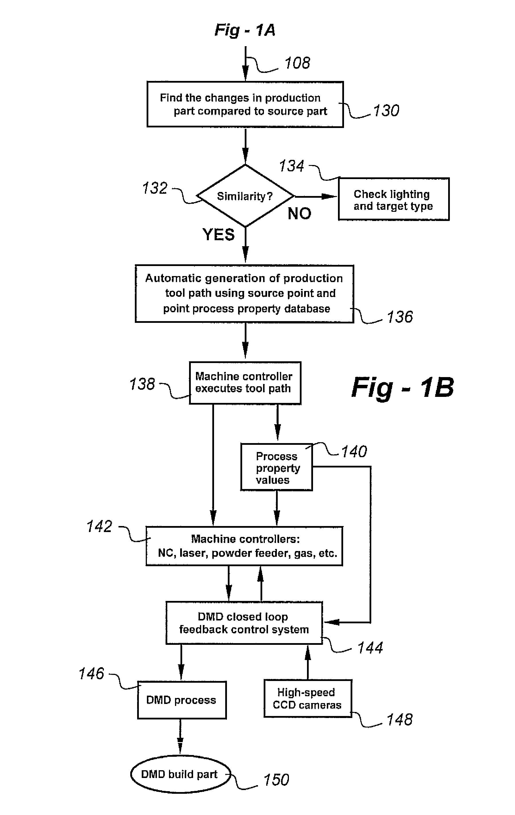
[0016]In the preferred embodiment, production cycle time is reduced by automatically generating new tool-paths to accommodate inaccuracies of each part, and to produce high-quality direct-metal deposition (DMD) parts using flexible process controls. The automatic tool-path generation is accomplished using a vision-system-based point and Point Process Property (PPP) database. High-quality deposition is achieved by feeding the vision system PPP to the DMD closed-loop feedback control system.

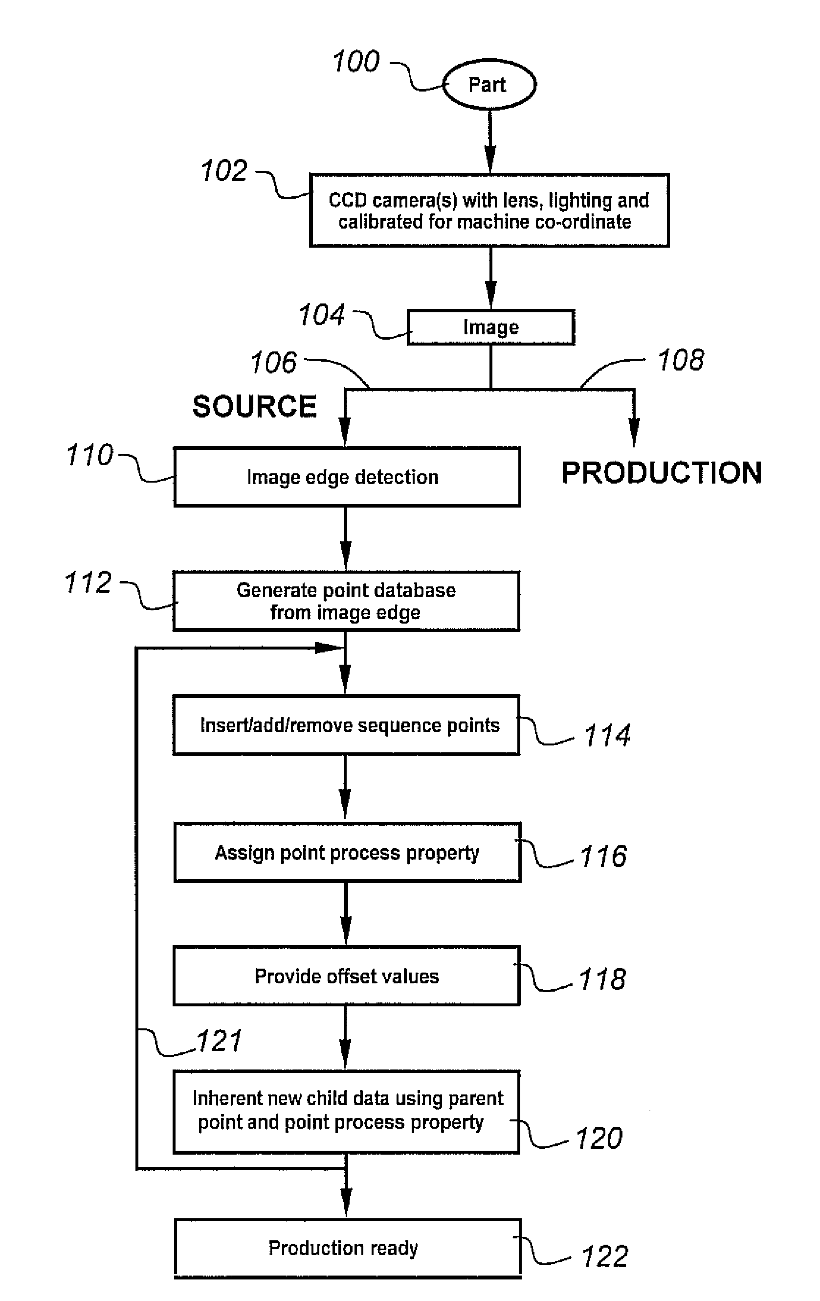
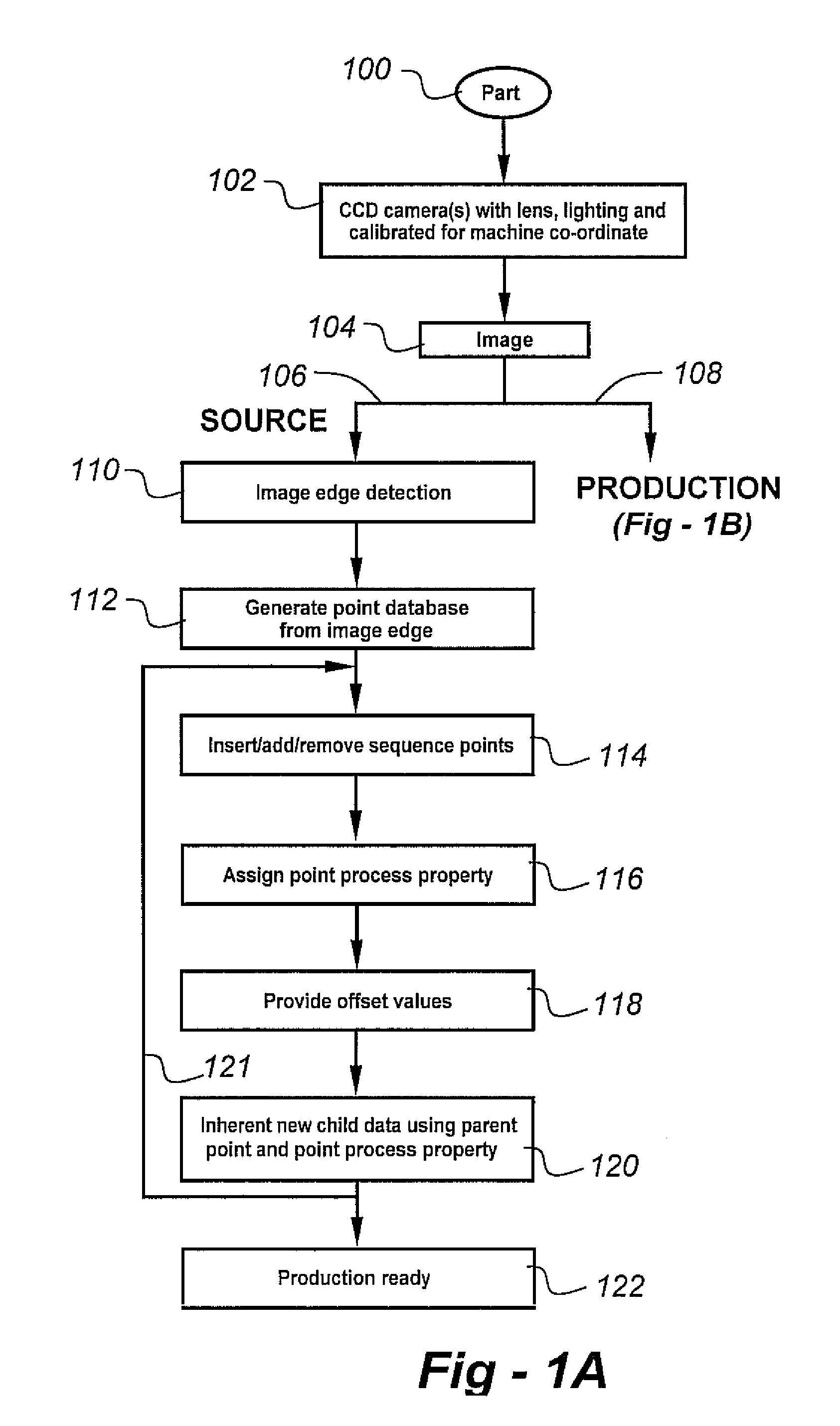
[0017]Referring to the flow chart of FIG. 1A, a part is provided at 100, and an image is taken at 104 using a CCD camera at 102. The first part is considered as a source part (106). A machine-coordinated, calibrated camera or cameras image the part and its edges are detected at 110. Based...


PUM

PropertyMeasurementUnit
Poweraaaaaaaaaa
Speedaaaaaaaaaa

Abstract

New tool paths are automatically created for rapid prototyping and additive manufacturing processes, facilitating the fabrication of new or repaired parts with superior geometries and/or compositional characteristics. The profile of a source part is imaged from camera picture and point wise offset adjustments. Part profile and process points are automatically generated without teaching by an operator. In the preferred embodiment, point-by-point process variable settings (i.e., laser power, speed and powder flow) are coupled to a closed-loop, direct-metal deposition (DMD) process to fabricate or repair production components using a tool path derived from the profile of the source part. The preferred method includes the steps of detecting the edge of the source part; generating a point-to-point database of the source part based upon the detected edge; and assigning one or more process parameters associated with the additive manufacturing process used to fabricate or repair the production part.

Description

REFERENCE TO RELATED APPLICATION[0001]This application claims priority from U.S. Provisional Patent Application Ser. No. 60 / 912,214, filed Apr. 17, 2007, the entire content of which is incorporated herein by reference.FIELD OF THE INVENTION[0002]This invention relates generally to rapid prototyping and additive manufacturing processes and, in particular, to a system and method whereby new tool paths are automatically created for superior geometries and / or compositional characteristics.BACKGROUND OF THE INVENTION[0003]Fabrication of three-dimensional metallic components via layer-by-layer laser cladding was first reported in 1978 by Breinan and Kear. In 1982, U.S. Pat. No. 4,323,756 issued to Brown et al., describes a method for the production of bulk rapidly solidified metallic articles of near-net shape, finding particular utility in the fabrication of certain gas turbine engine components including discs and knife-edge air seals. According to the disclosure, multiple thin layers o...

Claims


Application Information

Patent Timeline
IPC IPC(8): B05D3/06
CPCB23P6/007C23C4/12G06Q10/06312G06Q10/06314G06Q10/06315G06Q10/06316G05B19/4099G05B2219/49008G05B2219/49021B33Y50/02
Inventor BAGAVATH-SINGH, VIJAYAVELD'SOUZA, JOLLIN
Owner P O M GRP THE
Why Eureka
Try Eureka