Direct digital sampling method for radios

a radio and digital sampling technology, applied in the direction of digital-analog converters, electrical equipment, code conversion, etc., can solve the problems of direct sampling method limitations, jitter error directly affecting the dynamic range of the digitizing device, and the cost of such high-quality adc devices would override the cost savings made in the rf section, so as to reduce cross-coupling, reduce cross-coupling, and improve the effect of acp

Inactive Publication Date: 2008-10-23
AVIDYNE CORPORATION
View PDF13 Cites 9 Cited by
  • Summary
  • Abstract
  • Description
  • Claims
  • Application Information

AI Technical Summary

Benefits of technology

[0012]The Direct Digital Sample architecture used in the present invention has several advantages over the previous two Direct Conversion methods described. First, the problems of mixer IMD are eliminated since no frequency translation is required. This greatly reduces the impact of cross coupled interference from strong in-band or out-of-band signals. Second, the reduced cross-coupling from adjacent channels specifically improves the ACP. Third, the part count of RF components is reduced even over what is required for the Direct Conversion method. Fewer RF components will mean lower cost, size, weight, and power consumption, as well as significantly less factory alignment and calibration. Since the calibration process and other adjustments are all digital, and in general they do not drift with temperature, they are easier and cheaper to perform. Reliability and mean-time-between-failure (MTBF) are improved due to this part count reduction, and especially due to the reduction in sensitive RF and analog components. Finally, the Direct Sample method has the unique capability of simultaneously receiving and processing multiple channels within the receiver band, which does require duplication of circuitry in the VLSI processor and “baseband” DSP processor, but these are much easier and less expensive to implement than their analog counterpart would be.
[0019]An advantage of multiple sub-systems for a NAV / COMM is that it provides some independence between the navigation and communication functions thus minimizing the possibility of common mode failures. This enhances the utility of the device under failed or partially failed conditions. Another advantage is that the sample clock characteristics can be optimized for the frequency band used by each sub-system rather than compromising performance characteristics in order to use the same clock. It should be appreciated that any number of sub-systems, as well as any combination of components for each sub-system, may be employed. It should also be appreciated that the NavClk, ComClk, and TxClk sources need not be independent. Any number of clock sources may be employed and shared in any way.
[0021]In an embodiment of the invention, a method to frequency shift sub-system clock frequencies by more than a channel bandwidth, is employed. An advantage of this technique is that it can actively mitigate in-band spurious signals generated from the various sub-system clock sources. The clock frequency shifting is achieved by “pushing” known clock spurs to an unused adjacent channel, then compensating for this shift by adjusting the digital tuning of components that determine the RF operating frequency. This greatly lessens the mechanical and electrical isolation requirements needed to minimize cross-coupling effects between sub-systems. The spacing between sub-systems can be reduced while not increasing manufacturing costs or device size.
[0022]In an embodiment of the invention, a method of coupling an auxiliary dither signal onto a RF receiver input, allowing both of the signals to be digitized simultaneously by a high speed ADC, is employed. The auxiliary dither signal may be an FM modulated carrier with a very low modulation index. The auxiliary dither signal may also occupy only a guard band bandwidth and have amplitude nearly full scale of the ADC input range. Additionally, the auxiliary dither signal may be applied to the receiver signal immediately before an analog-to-digital conversion. Thus, dithering is applied after the last RF filter stage. The advantage of this technique is that the frequency of the dither signal may be significantly offset from the desired signal frequency and therefore easily removed after the ADC by digital processing methods. Therefore, no additional subtracting or filtering circuitry is needed. This technique greatly enhances the linear response of the ADC quantizer by improving factors such as cross modulation performance and spurious free dynamic range.
[0023]In another embodiment of the invention, a digital method of coupling an auxiliary dither signal onto the transmitter signal, allowing both of the signals to be digital to analog converted simultaneously by a high speed DAC, is employed. The transmitter auxiliary dither signal may be an FM modulated carrier with a very low modulation index. Since the frequency of the transmitter auxiliary dither signal may be significantly offset from the frequency of the desired signal, or in other words occupy an out-of-band bandwidth, it may have an amplitude nearly full scale of the DAC output device and may be easily removed from the transmitted signal, after the digital-to-analog conversion, by standard analog filtering techniques. The transmitter auxiliary dither signal is easiest to remove if it is generated near DC and only extends high enough in frequency to provide the required dithering effect.

Problems solved by technology

The Direct Sample method also has several limitations.
Until recent years the expense of such high quality ADC devices would override the cost savings made in the RF section.
Clock phase jitter error will directly affect the dynamic range of the digitizing device especially when under-sampling techniques are applied.
These types of clocks tend to be expensive at high frequency.
For a system like a NAV / COMM, these problems are further exacerbated by the complexity of integrating multiple receivers and a transmitter each of which occupy different VHF / UHF radio frequency bands and each require different bandwidths and different ADC clocking characteristics.
In addition, current Direct Sample VHF transmitters have not been viable for NAV / COMM systems because it has not been possible to meet transmitter spectral mask requirements while providing wide-band tuning capability.

Method used


Image

  • Direct digital sampling method for radios
  • Direct digital sampling method for radios
  • Direct digital sampling method for radios

Examples


Embodiment Construction

[0033]A description of example embodiments of the invention follows.

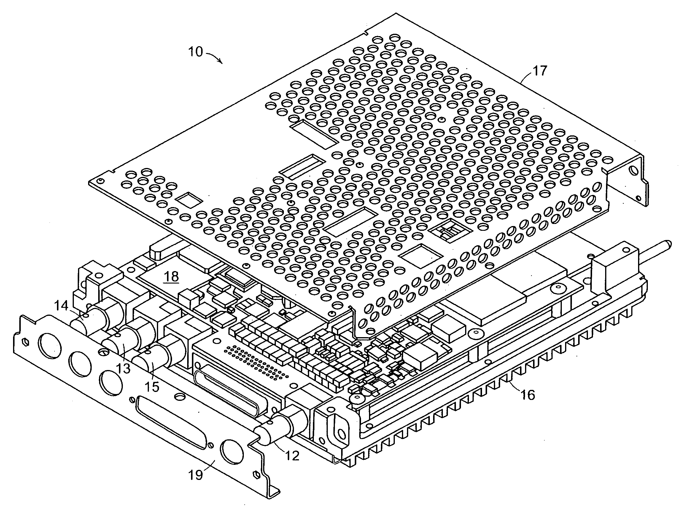
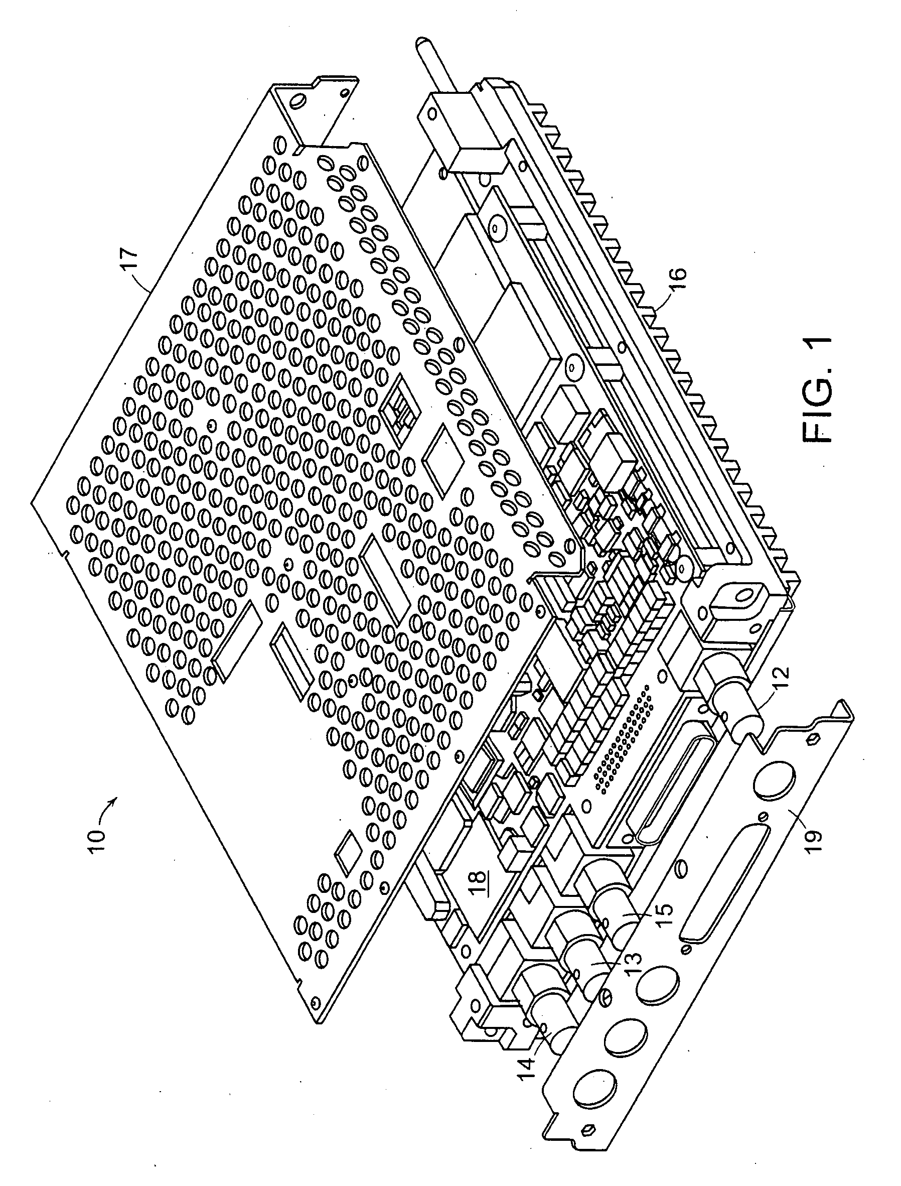
[0034]FIG. 1 illustrates a NAV / COMM radio embodiment of the present invention, referred to herein by the general reference numeral 10. The NAV / COMM system 10 comprises an antenna port for a VHF transceiver 12, an antenna port for a Localize / VOR receiver 13, an antenna port for a Glide Slope receiver 14, and an antenna port for a Marker Beacon receiver 15. The NAV / COMM system 10 also comprises circuitry 18 needed to signal process the RF receiver and transceiver signals. The circuitry 18 is enclosed in a chassis consisting of a metal heat-sink backplate 16, an RF shield cover plate 17, and an RF shield front plate 19.

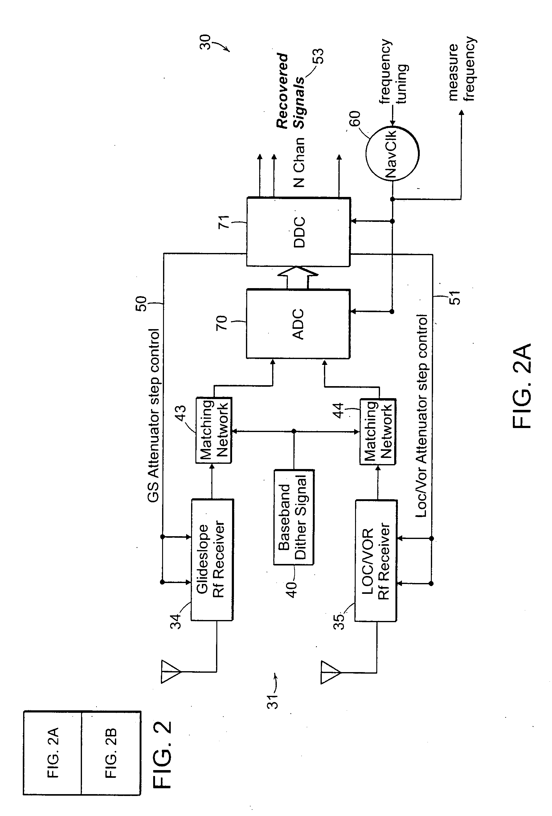
[0035]FIG. 2 illustrates an example receiver and transceiver embodiment of the present invention, referred to herein by the general reference numeral 30. It should be appreciated that other receiver and / or transceiver combinations may be employed in the NAV / COMM system. The NAV / COMM receiver and transcei...


PUM


Abstract

A direct digital sampling and synthesis general purpose radio system is disclosed which employs single or multiple receiver and / or transmitter sub-systems that require no analog frequency conversion or translation circuitry. Receiver signal processing is disclosed that describes methods of conditioning and digitizing an entire received RF signal band in which the down conversion, channelization and demodulation are performed digitally. In addition, a method for direct synthesis of transmitter signals is also disclosed where up conversion and carrier modulation is performed digitally. Several mitigation techniques are described which aid in overcoming device limitations as well as overcoming problems created by combining multiple digital transmitters and receivers into a single integrated system. One embodiment of the invention describes an integrated VHF / UHF aircraft NAV / COMM radio system which combines a VHF transmitter with four VHF / UHF receivers all of which require no IF circuitry. This embodiment allows for multiple simultaneous airborne radio services on a single platform such as voice and data communication modes (AM, ACARS, VDLM2, LAAS, etc.) as well as navigational modes such as VOR, ILS, and Marker Beacon. By utilizing direct digital methods, the signal processing burden is moved almost entirely to the digital domain where the processing can be optimized for each signal type and where linearity is guaranteed. Fewer RF components are required which result in less unit to unit variability, lower production costs, and improved reliability.

Description

BACKGROUND OF THE INVENTION[0001]The invention pertains to Very High Frequency / Ultra High Frequency (VHF / UHF) radio equipment installed on commercial and general aviation aircraft used for air-to-ground, ground-to-air, and air-to-air communication as well as radio navigation and instrument landing. As an example, the invention may combine a VHF transceiver operating on 118.0 MHz to 137.975 MHz, a Localizer / VHF Omni-directional Radio Range (VOR) receiver operating on 108.0 MHz to 117.950 MHz, an Instrument Landing System (ILS) Glide Slope receiver operating on 329.300 MHz to 335.0 MHz, and an ILS Marker Beacon receiver operating on 75.0 MHz into a modular package that may be remotely mounted or integrated with an Electronic Flight Information System (EFIS) chassis. The combination of a VHF transceiver with ILS and VOR receivers is common in the industry and is generally referred to as a NAV / COMM system.[0002]The typical NAV / COMM configuration in the current state of the art is to use...

Claims


Application Information

Patent Timeline
Patent Type & Authority Applications(United States)
IPC IPC(8): H04B7/00
CPCH03M1/0639H03M1/12H03M1/66
Inventor WAHAB, SAMI R.HAINES, DONALD MARKKYRIAKOS, CONSTANTINOS S.NICOTRA, ANTHONY
Owner AVIDYNE CORPORATION
Why Eureka
Try Eureka