Exhaust Gas Recirculation Mixer for a Turbo-Charged Internal Combustion Engine

Active Publication Date: 2008-10-30
VOLVO LASTVAGNAR AB
View PDF9 Cites 7 Cited by
  • Summary
  • Abstract
  • Description
  • Claims
  • Application Information

AI Technical Summary

Benefits of technology

[0004]An object of the invention is therefore to provide a com

Problems solved by technology

Unfortunately, in internal combustion engines for heavy trucks there is generally a lack of space in the engine compartment.
It is the

Method used


Image

  • Exhaust Gas Recirculation Mixer for a Turbo-Charged Internal Combustion Engine
  • Exhaust Gas Recirculation Mixer for a Turbo-Charged Internal Combustion Engine
  • Exhaust Gas Recirculation Mixer for a Turbo-Charged Internal Combustion Engine

Examples


Embodiment Construction

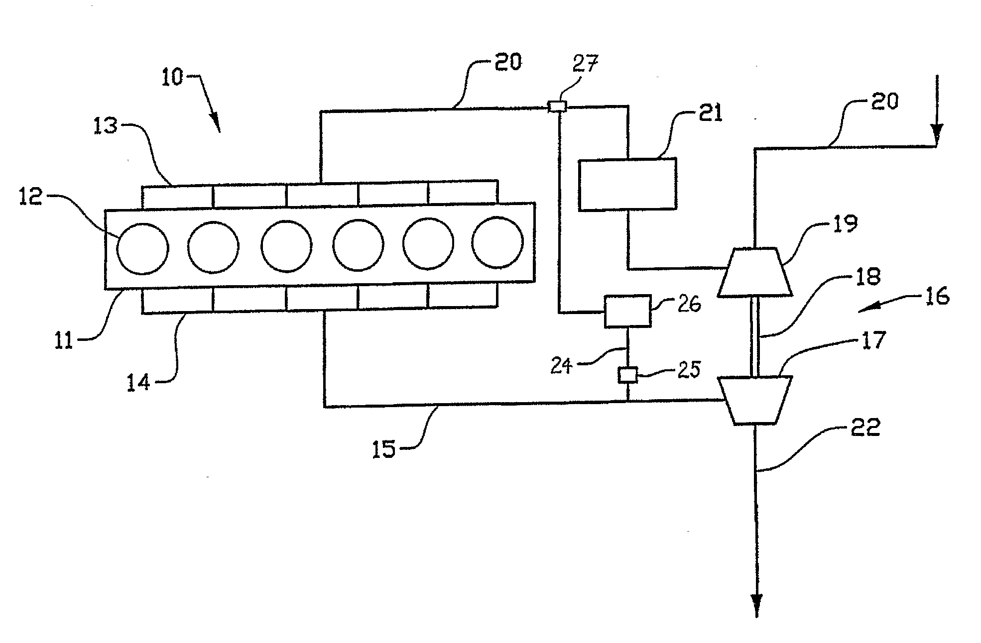
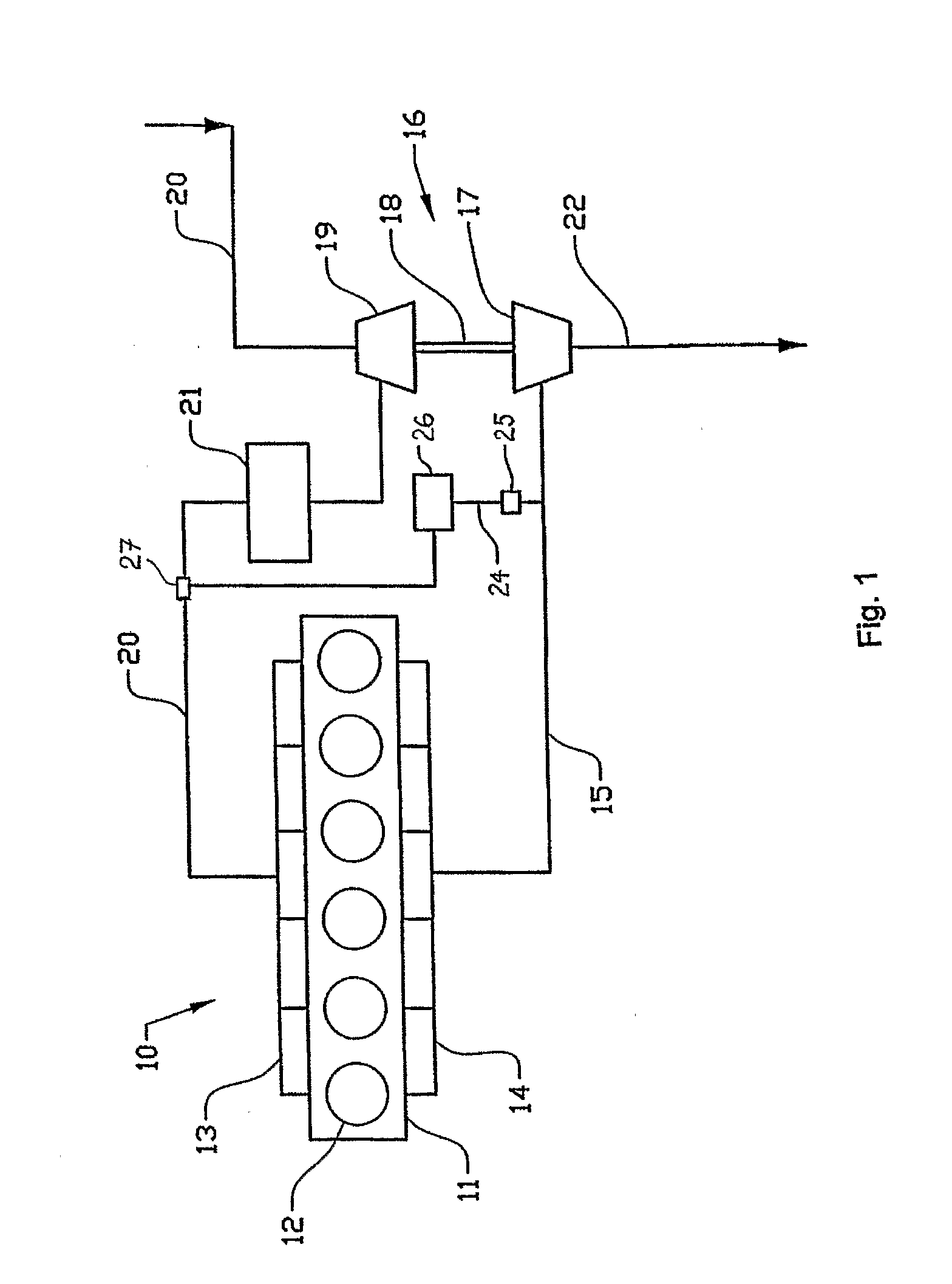
[0011]The internal combustion engine 10 represented schematically in FIG. 1 comprises an engine block 11 having six piston cylinders 12 with an inlet manifold 13 and an exhaust manifold 14. Exhaust gases are led via an exhaust pipe 15 to the turbine rotor 17 of a turbocharger unit 16. The turbine shaft 18 drives the compressor wheel 19 of the turbocharger unit, which via an intake line 20 compresses intake air and delivers this via an intercooler 21 to the inlet manifold 13. Fuel is fed to each cylinder 12 by way of injectors (not shown).

[0012]Exhaust gases that have passed through the turbocharger unit 16 are led into the atmosphere via the exhaust line 22. Exhaust gases are also returned to the intake side of the engine as so-called EGR gas, via a pipeline 24, for reduction of the engine nitrogen oxide emissions in accordance with the state of the art. This line comprises a valve 25, which serves as regulating valve for regulating the EGR flow. In addition there is a cooler 26 for...


PUM


Abstract

An EGR mixer arrangement for mixing gas into the intake air of a turbocharged internal combustion engine is provided. The arrangement includes an inlet port with connection for a branch pipe, which with an insertion section opens out into the inlet port. The insertion section forms a diffuser vane with a surface which is positively double-bent in the direction of flow of the intake air and which extends in a curved shape in the flow direction of the inlet port.

Description

TECHNICAL FIELD[0001]The present invention relates to an EGR mixer arrangement for mixing the gas into the intake air of a turbocharged internal combustion engine, comprising an inlet port with connection for a branch pipe, which with an insertion section opens out into the inlet port.BACKGROUND OF THE INVENTION[0002]The recirculation of exhaust gases, so-called Exhaust Gas Recirculation (EGR), is a commonly known method of influencing the combustion in internal combustion engines and means that a proportion of the total exhaust gas flow from the engine is returned in a secondary flow to the intake side of the engine where it is mixed with the intake air for delivery into the engine cylinders. When combustion occurs with a reduced oxygen content, due to EGR admixture, the combustion temperature is reduced. This makes it possible to reduce the quantity of nitrogen oxides (NOx) in the exhaust gas emissions discharged into the surrounding environment.[0003]The quantity of EGR gas that ...

Claims


Application Information

Patent Timeline
IPC IPC(8): F02B33/44
CPCF02B29/0406F02M25/0707F02M25/0722F02M25/0727H04L27/2601H04L2001/0097H04W40/28H04W52/40Y02T10/121F02M26/05F02M26/19F02M26/23
Inventor CARLSSON, ANNIKABLAGIC, STANIMIR
Owner VOLVO LASTVAGNAR AB
Why Eureka
Try Eureka