Electrical connection of energy harvesting devices

a technology of energy harvesting device and electrical connection, which is applied in the field of electric power harvesting system and method, can solve the problems of inability to directly power an electrical device, inability to use and replace batteries, and inability to meet the needs of use, and achieves the effect of higher voltage or output curren

Inactive Publication Date: 2008-10-30
HONEYWELL INT INC
View PDF11 Cites 49 Cited by
  • Summary
  • Abstract
  • Description
  • Claims
  • Application Information

AI Technical Summary

Benefits of technology

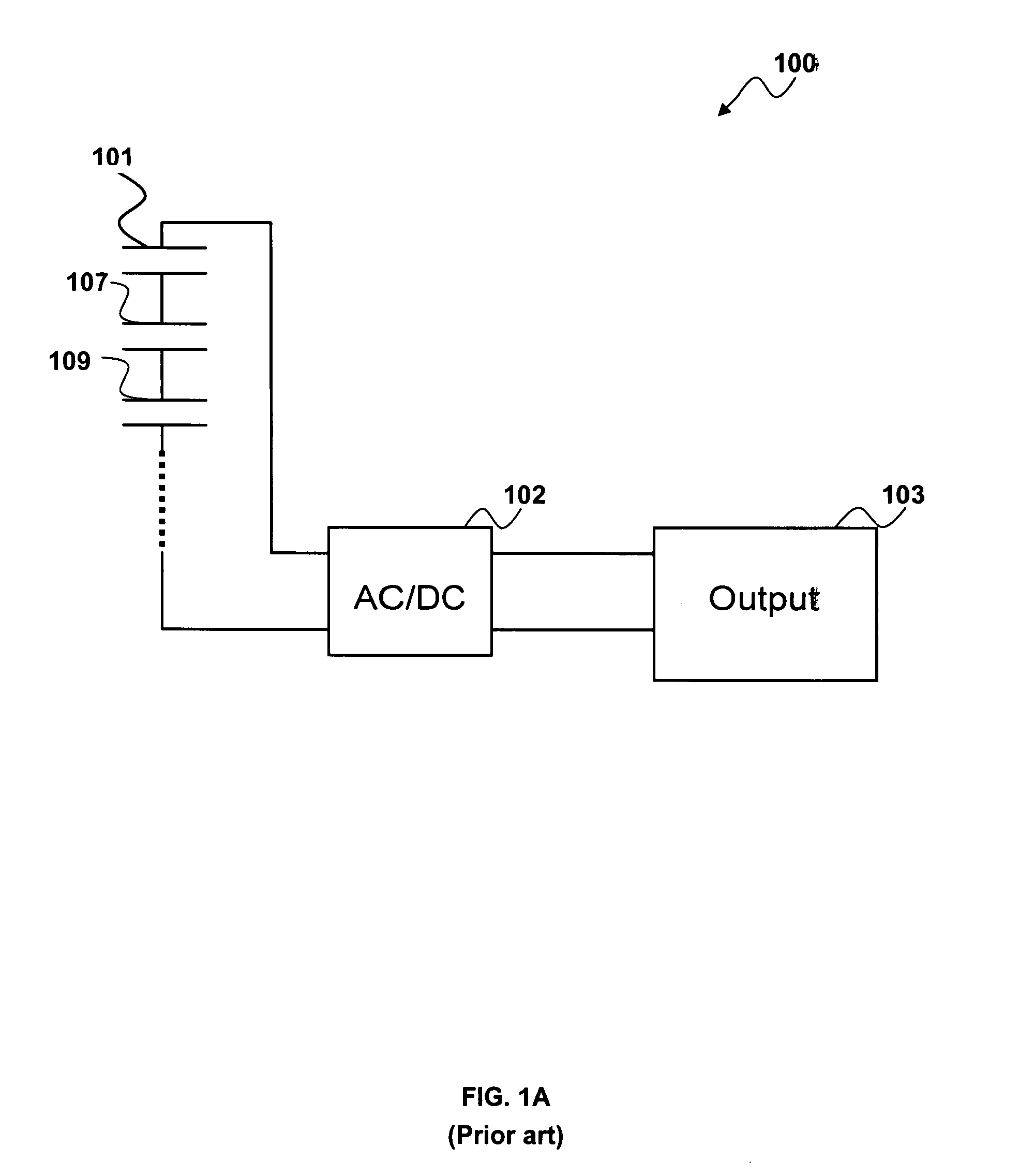
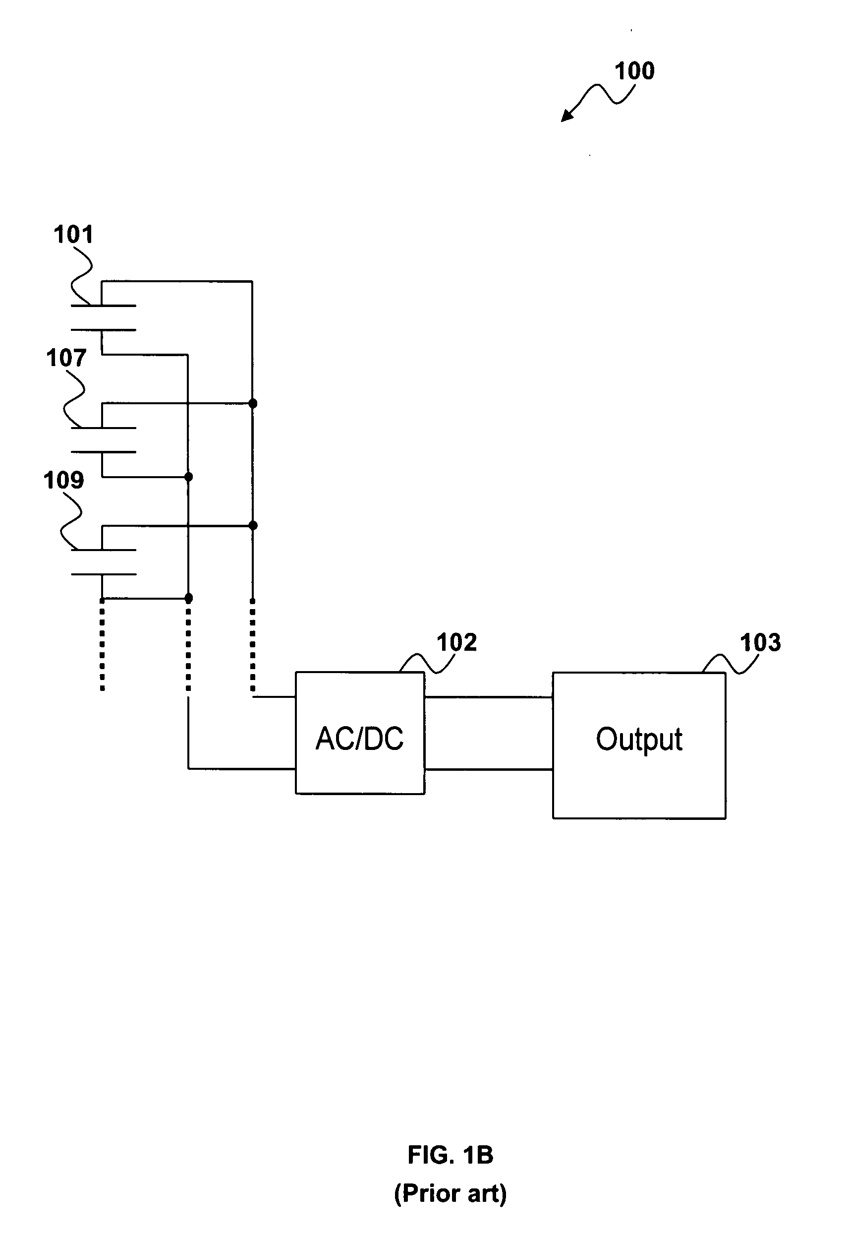
[0015]The use of a cantilever array (i.e., clamped component) can overcome issues of frequency and power output encountered with the case of a single cantilever. When the cantilevers are electrically connected directly, the AC electrical power from different cantilever can be counteracted due to their different phases. Instead of electrically connecting the cantilevers of an energy harvesting device directly, the AC output can be rectified to a DC output. The DC output terminals can be connected in parallel or in series to achieve a higher voltage or output current. The connection circuitry, including the rectifying components, can be integrated with one or more micro cantilevers into a single IC chip.

Problems solved by technology

In many applications, however, utilizing and replacing batteries, even long-lived battery types, is impractical due to factors such as, but not limited to, hard-to-access locations, and labor and replacement battery costs.
The energy produced by these materials in many cases, however, is much too small to directly power an electrical device.
One single cantilever can only function in a single frequency and produces a very limited power output.
The connection method thus cannot achieve ideal results.

Method used


Image

  • Electrical connection of energy harvesting devices
  • Electrical connection of energy harvesting devices
  • Electrical connection of energy harvesting devices

Examples


Embodiment Construction

[0029]The particular values and configurations discussed in these non-limiting examples can be varied and are cited merely to illustrate at least one embodiment and are not intended to limit the scope thereof.

[0030]FIG. 2 illustrates a process flow diagram depicting a method 100 for fabricating a cantilever, in accordance with a preferred embodiment. A general flow process is depicted in FIG. 2 with respect to illustrative steps [1], [2], [3]. [4], [5], and [6]. As indicated at step [1], a (100) oriented silicon substrate 201 of 500 μm thickness, can be wet-oxidized. Note that the value of 500 μm is merely an illustrative and suggested value only and is not considered a limiting feature of the embodiments. The same is also true for other parameters and values discussed herein. A layer of 2 μm thick silicon oxide 202 serves to improve the adhesion of a functional layer to the silicon substrate 201 surface and can act as a mask during a later-implemented wet etching operation.

[0031]Th...


PUM

PropertyMeasurementUnit
thicknessaaaaaaaaaa
bias voltageaaaaaaaaaa
vibration strengthaaaaaaaaaa

Abstract

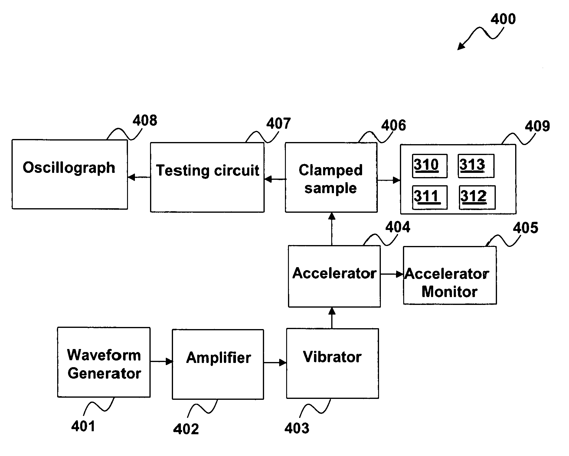
An energy harvesting system and method. An array of cantilevers with PZT films is electrically connected to an energy harvesting device that converts vibration energy to electrical energy. An AC output signal provided by the cantilevers can be rectified to a DC output, thereby avoiding impairment in total electrical output. The DC output terminals can be connected in parallel and / or in series in order to achieve a higher voltage and / or a higher current that prevents the output from different cantilevers from counteracting one another. The connection circuitry includes one or more rectifying components integrated with one or more micro-cantilevers into a single integrated circuit chip. An oscillograph can be utilized to monitor the DC output voltage signal from an associated testing circuit.

Description

TECHNICAL FIELD[0001]Embodiments are generally related to electrical power harvesting systems and methods. Embodiments are also related to piezoelectric energy harvesting devices. Embodiments are additionally related to connection circuitry for energy harvesting.BACKGROUND OF THE INVENTION[0002]Power conservation is an important factor in many electrical systems, such as but not limited to, wireless sensor networks (WSNs) that operate according to low power requirements and low data rates. Long battery life (e.g., up to 10 years) is essential in such systems where line power is not available or if the system is mobile in nature. In many applications, however, utilizing and replacing batteries, even long-lived battery types, is impractical due to factors such as, but not limited to, hard-to-access locations, and labor and replacement battery costs. Accordingly, solutions have been sought for harvesting or extracting electrical power from the environment.[0003]Energy harvesting device...

Claims


Application Information

Patent Timeline
Patent Type & Authority Applications(United States)
IPC IPC(8): G01N27/00
CPCG01N29/022G01N29/2481G01N2291/106
Inventor MAO, XINHUIFANG, HUABIN
Owner HONEYWELL INT INC
Why Eureka
Try Eureka