
Two-stage ignition system

a two-stage ignition and gas flow technology, applied in the direction of rocket engine plants, machines/engines, anti-theft devices, etc., can solve the problems of failure of the method to produce the final elevated temperature combustion product, failure of the payload in a useless orbit, and catastrophic loss of the payload, so as to improve the overall ignition system reliability, increase the operational life, and reduce the stress on the igniter

Inactive Publication Date: 2008-10-30
KTE ENG
View PDF99 Cites 47 Cited by
  • Summary
  • Abstract
  • Description
  • Claims
  • Application Information

AI Technical Summary

Benefits of technology

[0018]The relatively benign heating environment of this pilot stage compared to the main combustion stage (and thus current art torch igniter systems) reduces stress on the igniter improving overall ignition system reliability and increasing operational life. This seclusion of the igniter to the pilot stage likewise allows for the elevated temperature combustion product resulting from the main combustion stage to use higher propellant flows and have higher temperatures than most current art systems. This serves to allow the elevated temperature combustion product to be used for a variety of applications for which a current art ignition system would be inadequate.
[0019]The present invention enables the same design to be used for multiple uses in different rocket systems or subsystems that need a flow of elevated temperature combustion product, lowering non-recurring development costs, increasing production economies of scale and thus lowering recurring hardware acquisition costs. These different rocket systems include, but are not limited to, main rocket engine torch ignition, propellant conditioning heaters, turbomachinery preburners, and small rocket engines, such as reaction control system thrusters.

Problems solved by technology

Interrupting this series of precise, time-synchronized events with a significant time lag generally leads to failure of the method to produce its final elevated temperature combustion product.
Failed ignition in flight can leave a payload in a useless orbit or even cause a catastrophic loss of the payload.
Rocket engine ignition (and re-ignition for restartable engines) has historically been a significant source of unreliability for space launch vehicles, and the main cause of a number of mission failures.
Among others, in-flight Ariane rocket mission failures occurred due to third stage HM-7B rocket engine ignition failure on 12 Sep. 1985 for an Ariane 3 and on 31 May 1986 for an Ariane 2.1 Similarly, two launches of Japan's LS-4 rocket in the mid-1960s, and a series of launches of the Russian LV Molniya launch vehicle in the 1960s all failed due to upper stage engine ignition failures.
Engine ignition failure has also been blamed for costly launch vehicle aborts on the launch pad such as for a 28 Jan. 1999 Delta II launch attempt which was aborted due to first stage vernier engine ignition failure.
Failed ignition on the launch pad can also possibly result in unburned engine fuel and oxidizer expelled from the rocket engine onto the launch pad which could, in-turn, cause an explosion.
The start-up of rocket engines, including initiation of combustion, is a complex, dynamic process that challenges rocket engine designers due to the possible presence of combustion instabilities and vibrations that can cause operational inefficiencies, structural damage, or even catastrophic engine failure.
One such instability is a hard start, caused when too much propellant enters the combustion chamber prior to ignition and the resultant rate of build-up of combusted gasses results in an excessive pressure spike.
Another instability example is combustion vibration sometimes caused when combustion chamber pressure rises too slowly due to a temporary too low injector pressure drop during thrust build-up.
Further, propellant flows that are too strong can quench the ignition spark or flame.
Timing errors as short as a few tens of milliseconds can potentially cause hard starts or even engine failures.
The performance of some spark-torch igniter systems is sensitive to oxidizer-to-fuel mixture ratio, flow rates, excitation voltage, and spark rate, making the system relatively complex.
Catalytic-torch igniters have been studied extensively and successfully applied to ground systems but have had only limited application to date on rockets.
These chemicals are highly corrosive, toxic, and ignite spontaneously on contact with air, and are thus expensive and risky to use.
These relatively high flow rates generally result in high temperature igniter flows which, combined with the proximity of many embodied detection devices to the very hot rocket engine combustion chamber, tend to reduce lifetime and reliability of devices used to detect successful igniter operation.
However, the reliability of the safety interlocks has been less than ideal and accurate, reliable detection of proper ignition system operation is challenging.
However, this method can be compromised by wire breakage caused by wind or incomplete burn-through of the wires due to improper placement.
Pressure sensors, thermocouple sensors, and cameras to detect electromagnetic spectra such as infrared are also sometimes used, but these methods have not been generally highly reliable due to the very challenging environment (very high acoustic, acceleration, and thermal loads) in the vicinity of a rocket's engine.
Further, rocket engine ignition systems are generally uniquely designed, developed, and fabricated to their particular application and thus generally very unique and are not reused among various rocket subsystems, even though they share common functional needs (e.g., rocket engine ignition, reaction control system ignition, propellant conditioning system ignition, etc.) Due to this uniqueness and very small economies of scale, rocket engine ignition systems have high non-recurring development and recurring hardware costs.
Conventional single stage ignition devices are limited by their single stage design.

Method used


Image

  • Two-stage ignition system
  • Two-stage ignition system
  • Two-stage ignition system

Examples


Embodiment Construction

I. Overview of the Invention

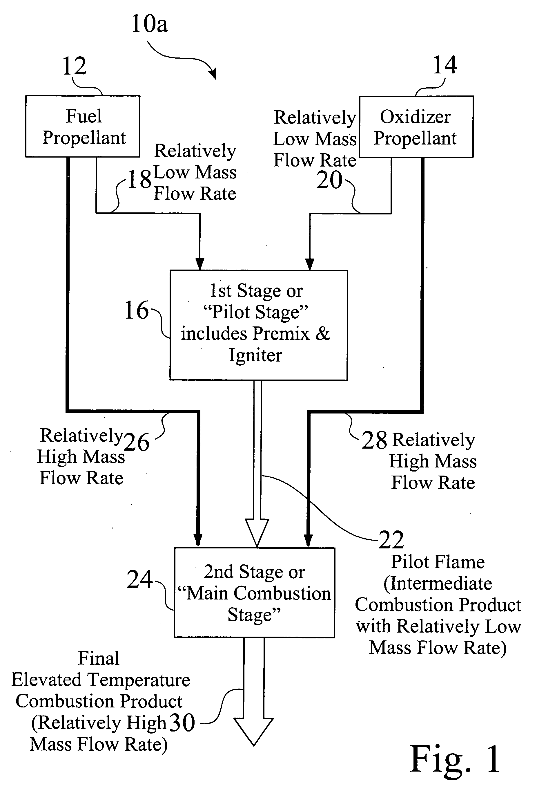
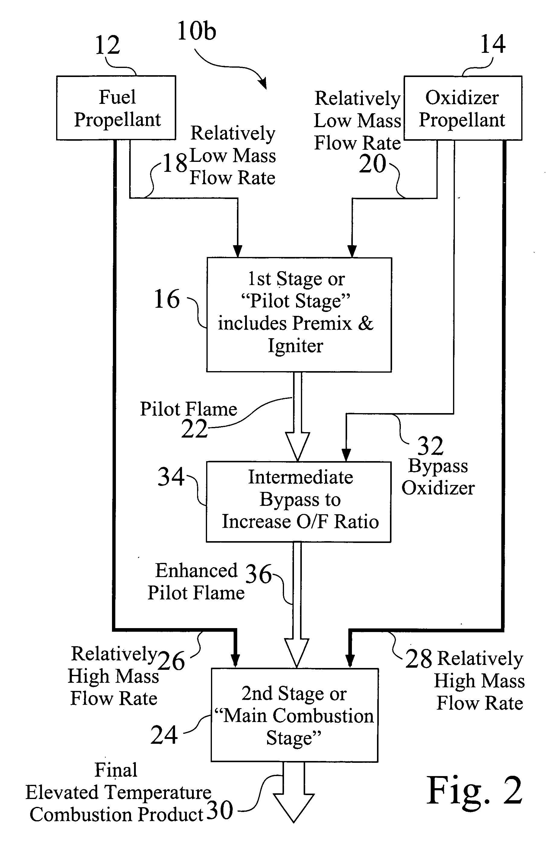
[0028]One embodiment of the present invention comprises a two-stage ignition method for creating a flow of elevated temperature combustion product using bipropellants. In one particular embodiment, the invention utilizes two different ignition stages, a “pilot stage,” which ignites relatively low mass flow rates of bipropellants to create a pilot flame, and a “main combustion stage,” which utilizes the pilot flame to ignite relatively high mass flow rates of bipropellants to produce a flow of elevated temperature combustion product.

II. Preferred & Alternative Embodiments of the Invention

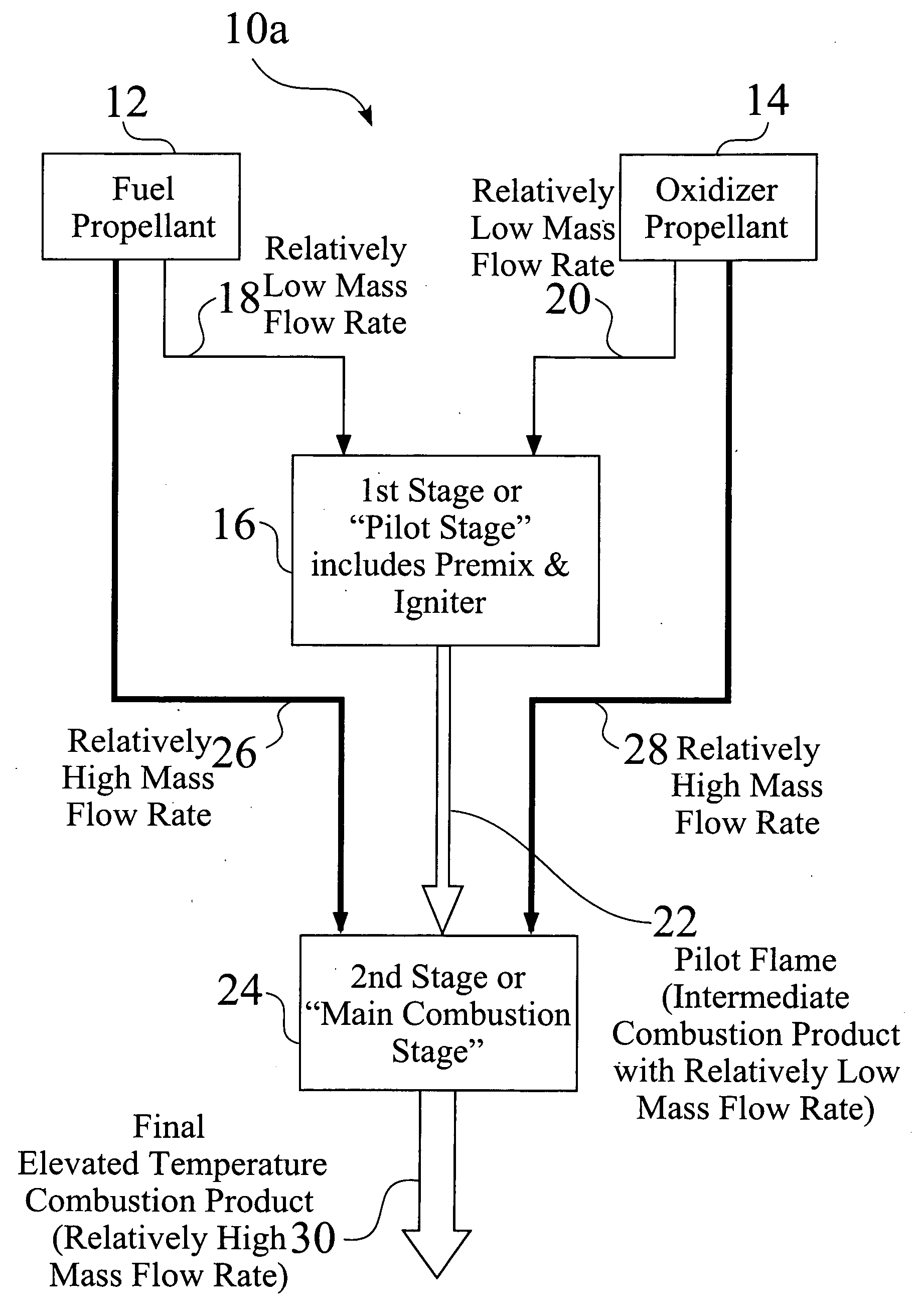
[0029]FIG. 1 is a flow chart which illustrates one particular embodiment 10a of the invention. A fuel propellant 12 and an oxidizer propellant 14 are introduced into a first or pilot stage 16, where the propellants are pre-mixed. The pilot stage 16 includes an igniter. Both the fuel propellant 12 and the oxidizer propellant 14 are introduced into the pilot stage 16 at a re...


PUM


Abstract

Methods and apparatus for providing a Two-Stage Ignition System are disclosed. In one embodiment of the invention, a pilot stage (16) is employed to ignite a plurality of propellants (12, 14) and to create a pilot flame (22). The plurality of propellants (12, 14) are ignited in the main combustion stage (24) using the pilot flame (22), and a flow of an elevated temperature combustion product (30) is produced.

Description

CROSS-REFERENCE TO A RELATED PROVISIONAL PATENT APPLICATION & CLAIM FOR PRIORITY[0001]The Present Non-Provisional patent application is related to Pending Provisional Patent Application Ser. No. 60 / 907,084, filed on 19 Mar. 2007, entitled Catalytic Combustion Device for Space Vehicle Applications. The Applicants hereby claim the benefit of priority under 35 U.S.C. Sections 119 or 120 for any subject matter which is commonly disclosed in the Present Non-Provisional patent application and Pending Provisional Patent Application Ser. No. 60 / 907,084.FEDERALLY SPONSORED RESEARCH OR DEVELOPMENT[0002]The Applicants developed some of the Inventions described in the Present Non-Provisional Patent Application under a Contract with NASA Glenn Research Center, Contract No. NNC06CB27C.FIELD OF THE INVENTION[0003]The present invention pertains to methods and apparatus for igniting a gas flow. More particularly, one preferred embodiment of the invention comprises a two-stage ignition method for cre...

Claims


Application Information

Patent Timeline
Patent Type & Authority Applications(United States)
IPC IPC(8): F02P21/00F02P7/00
CPCF02K9/42F02K9/95F02P15/001F02P23/04
Inventor SISK, DAVID B.SAKS, GREG Z.
Owner KTE ENG
Learn More