Hydrocarbon Recovery Facilitated by in Situ Combustion Utilizing Horizontal Well Pairs

Active Publication Date: 2008-10-30
CENOVUS ENERGY
View PDF4 Cites 26 Cited by
  • Summary
  • Abstract
  • Description
  • Claims
  • Application Information

AI Technical Summary

Benefits of technology

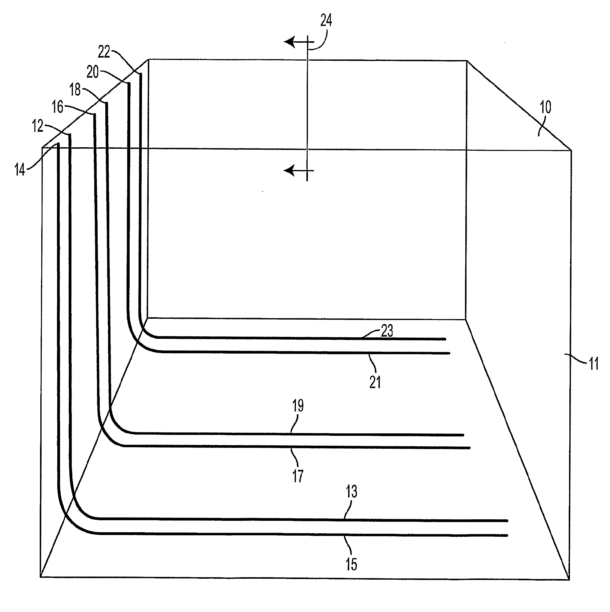
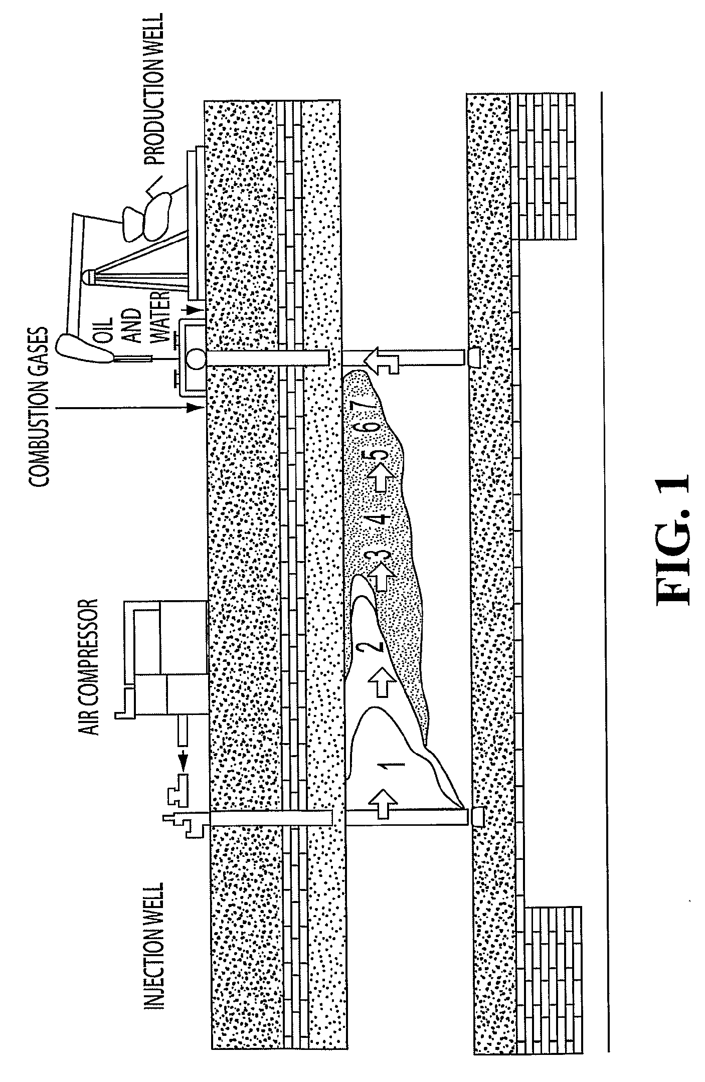
[0019]In some embodiments, the processes of the invention may involve injecting an oxidizing gas, such as air, enriched air, diluted air or another gas containing oxygen, into the formation, for example through the oxidizing gas injection well, to support in situ combustion in the formation. The in situ combustion may then be managed so as to mobilize hydrocarbons in the heavy oil. Fluids may be produced from the combustion gas production well, for example in a manner that directs combustion gases to the combustion gas production well. Mobilized hydrocarbons may be recovered from the formation through the hydrocarbon production well, for example by pumping fluids to the surface of the well. Fluids produced from a hydrocarbon production well may, from time to time, include a significant proportion of combustion gases. In some embodiments, the invention accordingly contemplates steps to control fluid flow within the reservoir to adjust the pressure, temperature and nature of produced and injected fluids, so as to achieve, on occasion, the production of hydrocarbons from production wells and the injection of oxidizing gases at injection wells. In some embodiments, the production rates of fluids

Problems solved by technology

There are extensive deposits of viscous hydrocarbons around the world, including large deposits in the Northern Alberta tar sands, that are not amenable to standard oil well production technologies.
The primary problem associated with producing hydrocarbons from s

Method used


Image

  • Hydrocarbon Recovery Facilitated by in Situ Combustion Utilizing Horizontal Well Pairs
  • Hydrocarbon Recovery Facilitated by in Situ Combustion Utilizing Horizontal Well Pairs
  • Hydrocarbon Recovery Facilitated by in Situ Combustion Utilizing Horizontal Well Pairs

Examples


example

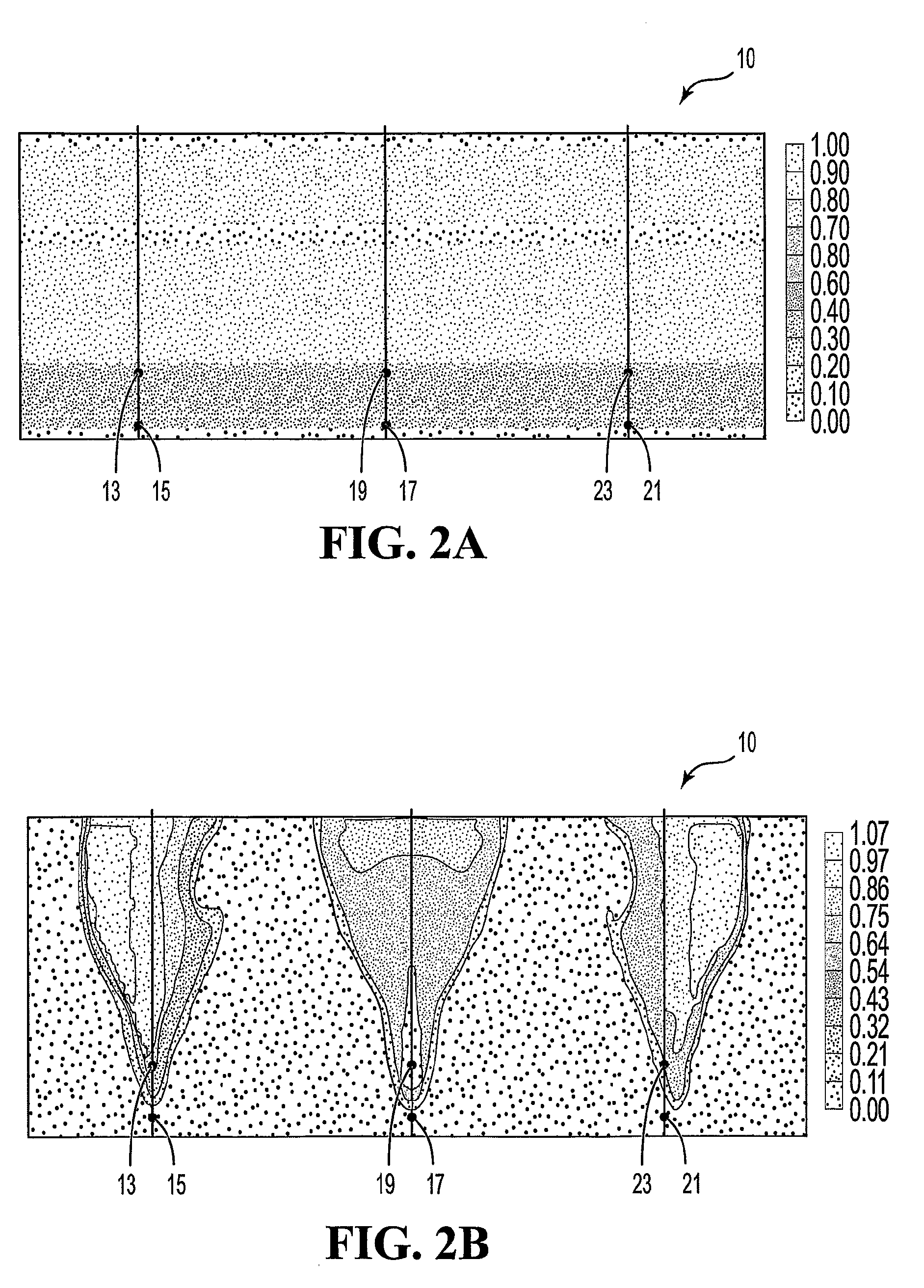
[0060]Processes of the invention have been modeled in a computer simulation, based on a selected location (CL). Various aspects of the performance of the processes of the invention in the simulation are illustrated in FIGS. 1 to 8. The simulation modeled interactions between injected air, combustion gases and hydrocarbons within the reservoir. The model tracked the behaviour of seven components: heavy oil / bitumen, water, methane, carbon dioxide, nitrogen / carbon monoxide, oxygen and coke.

[0061]FIGS. 3A to 3D illustrate a time series of temperature profiles in the modeled reservoir during recovery by in situ combustion processes of the invention. FIG. 3B shows ignition and initiation of combustion at the injection well of the central reservoir. FIGS. 3C and 3D show the combustion front rising from the central oxidizing gas injection well toward the top of the central reservoir chamber, and spreading laterally into adjacent reservoir chambers. In some embodiments, the invention accordi...


PUM


Abstract

The invention provides hydrocarbon recovery processes that may be utilized in heavy oil reservoirs. Horizontal hydrocarbon production wells may be provided below horizontal oxidizing gas injection wells, with distant combustion gas production wells offset from the injection well by a distance that is greater than the hydrocarbon production well offset distance. Oxidizing gases injected into the reservoir through the injection well support in situ combustion, to mobilize hydrocarbons. The process may be adapted for use in a reservoir that has undergone depletion of petroleum in a precedential petroleum recovery process, such as a steam-assisted-gravity-drainage process, leaving a residual oil deposit in the reservoir as well as mobile zone chambers. Processes of the invention may be modulated so that a portion of the residual oil supports in situ combustion, while a larger portion of the residual oil is produced, by channelling combustion gases along the pre-existing mobile zones with the reservoir.

Description

FIELD OF THE INVENTION[0001]The present invention relates generally to oil recovery processes, particularly thermal recovery processes that may be used in oil sands. In some embodiments, the processes of the invention utilize horizontal well pairs in heavy oil reservoirs, such as oil sands, to support production of hydrocarbons mobilized by in situ combustion. Aspects of the invention may for example be practiced following previous depletion of a reservoir. In particular, the invention provides a secondary recovery process that may advantageously be practiced following an initial recovery process utilizing the same horizontal well pairs.BACKGROUND OF THE INVENTION[0002]A variety of processes are used to recover viscous hydrocarbons, such as heavy oils and bitumen, from underground deposits. There are extensive deposits of viscous hydrocarbons around the world, including large deposits in the Northern Alberta tar sands, that are not amenable to standard oil well production technologi...

Claims


Application Information

Patent Timeline
IPC IPC(8): E21B43/243
CPCE21B43/243
Inventor CHHINA, HARBIR S.NZEKWU, BEN
Owner CENOVUS ENERGY
Why Eureka
Try Eureka