
Methods Of Manufacturing Paint Roller Covers From A Tubular Fabric Sleeve

a tubular fabric and paint roller technology, applied in the field of manufacturing paint roller covers, can solve the problems of inability of sliver knitting machines to produce tubular knitted pile fabrics, material costs and labor costs, and the cost of coating materials, so as to facilitate the mass production of paint roller covers, facilitate the manufacture, and durable and long-lasting

Active Publication Date: 2008-10-30
SEAMLESS TECH
View PDF9 Cites 20 Cited by
  • Summary
  • Abstract
  • Description
  • Claims
  • Application Information

AI Technical Summary

Benefits of technology

[0041]The melted lower melting point component of the low melt yarn used in the backing or base of the tubular knitted pile fabric flows into the cylindrical form of the outside of the cylindrical mandrel. The melted lower melting point component also flows between the backing loops and the central and / or intermediate portions of the sliver fibers or the loops of the cut pile yarn segments, and locks the sliver fibers or cut pile yarn segments into the tubular knitted pile fabric. This greatly reducing the degree of shedding of pile fibers from the tubular knitted pile fabric. It also converts the backing from a fabric into a unitary cylindrical assembly which, when cooled, will become substantially rigid. The mandrel is then cooled or allowed to cool, after which the rigid, cylindrical pile fabric assembly is removed from the mandrel.
[0042]In an alternate embodiment, one or more layers of a dry adhesive film may be first wound on a non-stick mandrel, following which the tubular knitted pile fabric segment is placed over the dry adhesive film. The mandrel is then heated to cause the dry adhesive film and the lower melting point component of the low melt yarn used in the backing or base of the tubular knitted pile fabric to melt together with the adhesive bonding material to create an even more rigid cylindrical assembly having a pile surface.
[0044]It may therefore be seen that the present invention teaches a method by which a paint roller cover may be manufactured from tubular knitted pile fabric. Further, in practicing the paint roller cover manufacturing method of the present invention, the tubular knitted pile fabric need not be stretched, and no wrinkles or other surface defects are introduced into the tubular knitted pile fabric during the manufacturing process. Still further, the paint roller cover manufacturing method of the present invention, which manufactures the tubular knitted pile fabric with the pile side out, does not require the tubular knitted pile fabric to be inverted during the manufacturing process.
[0045]The paint roller cover manufacturing method of the present invention results in an acceptable pile which extends from an acceptably rigid core which can be installed on and used with any conventional paint roller frame, or on a frame uniquely designed for the paint roller utilizing the new core design. The paint roller cover manufacturing method of the present invention facilitates either the manufacture of a paint roller cover of a desired finished length, or the manufacture of an extended length segment from which segments of any desired size can be cut for finishing as paint roller covers, thereby facilitating the mass manufacture of paint roller covers. The paint roller cover manufacturing method of the present invention can use either tubular sliver knitted pile fabric or tubular knitted yarn cut pile fabric as well as a number of different backing materials.
[0046]The paint roller cover manufacturing method of the present invention results in a construction which is both durable and long lasting, and yields a paint roller cover of superior quality. The paint roller cover manufacturing method of the present invention also reduces the cost of manufacturing paint roller covers when compared to conventional methods of manufacturing paint roller covers by manufacturing paint rollers without using a core member, thereby affording it the broadest possible market. Finally, all of the aforesaid advantages and aspirations of the paint roller cover manufacturing method of the present invention are achieved without incurring any substantial relative disadvantage.

Problems solved by technology

Such circular sliver knitting machines are incapable of either producing tubular knitted pile fabric segments having the pile on the outside or small diameter tubular knitted pile fabric segments.
Both the standard length rolls of knitted pile fabric strips and the rolls of extended length knitted pile fabric strips have substantial material costs and labor costs that are incurred in the manufacturing process after the circular knitting process.
The material costs include the cost of the coating material, losses due to fly (fly are extra fibers that come loose from the knitted pile fabric), losses during the cutting of the sixty inch (1524 millimeter) wide fabric segment into twenty knitted pile fabric strips, and seam losses throughout the operation.
The labor costs include the costs to perform the coating process, the brushing, the second pass shearing, and all of the finishing steps within the traditional sliver knit operation including slitting and continuously coiling the fabric slits.
However, all paint roller covers manufactured using the methods described above have a seam.
The seam inevitably produces a less than optimal paint roller cover since a seam can interfere with the uniform application of paint from the paint roller cover.
Errors resulting in overlapped fabric or gaps in the contiguous winding process often occur, resulting in increased scrap or marketing poor quality covers.
Such seams have the potential, particularly with short nap paint roller covers, to produce a seam mark or stippling effect on the surface being painted, particularly if the paint being applied combines with the seams to produce a more pronounced defective characteristic in the surface being painted.
This approach is certainly far too expensive to represent a viable solution, and would not compare well to currently commercially available paint roller covers in the quality of the paint coat that could be applied.
As such, the apparatus disclosed in Moore is incapable of manufacturing a knitted sleeve in which the pile is located on the exterior of the sleeve.
The problem that has prevented the inventions of the Arnold Schmidt patents and the Sannipoli et al. patents from being either practical or commercially successful is that the process of inverting a tubular knitted sleeve having the pile on the interior of the sleeve inevitably damages the fabric of the tubular knitted sleeve.
Not only is this process difficult and expensive, but it also results in variable density of the fabric as well as introducing the prospect of adhesive or thermoplastic bleed-through within the stitches.
Such problems will result in unacceptable product quality in paint roller covers made from this type of fabric.
The first drawback of the inverting method is that it requires a high degree of manual operation in that it requires cutting of the tubular knitted sleeves to size and placement of the tubular knitted sleeves into the tubes of the inverting machine.
The second drawback of the Sannipoli et al. method is that only relatively short length tubular knitted sleeves representing a single paint roller cover (typically nine inches (229 millimeters)) can be processed at a time, which makes the method inherently unsuitable for mass production.
The third, and by far the most serious, drawback of the Sannipoli et al. method is that the process of inverting the tubular knitted sleeves inevitably results in stretching the tubular knitted sleeves so that they will not snugly fit on the paint roller cover cores, potentially creating creases in a high percentage of them when they are adhesively secured to the paint roller cover cores.
This results in an unacceptably high percentage of them being defective and necessitating them being scrapped, resulting in an unacceptably high scrap cost.
Predictably, the inventions taught in the Sannipoli et al. patents and the Arnold Schmidt patents have never found commercial acceptance due to these serious disadvantages.

Method used


Image

  • Methods Of Manufacturing Paint Roller Covers From A Tubular Fabric Sleeve
  • Methods Of Manufacturing Paint Roller Covers From A Tubular Fabric Sleeve
  • Methods Of Manufacturing Paint Roller Covers From A Tubular Fabric Sleeve

Examples


Embodiment Construction

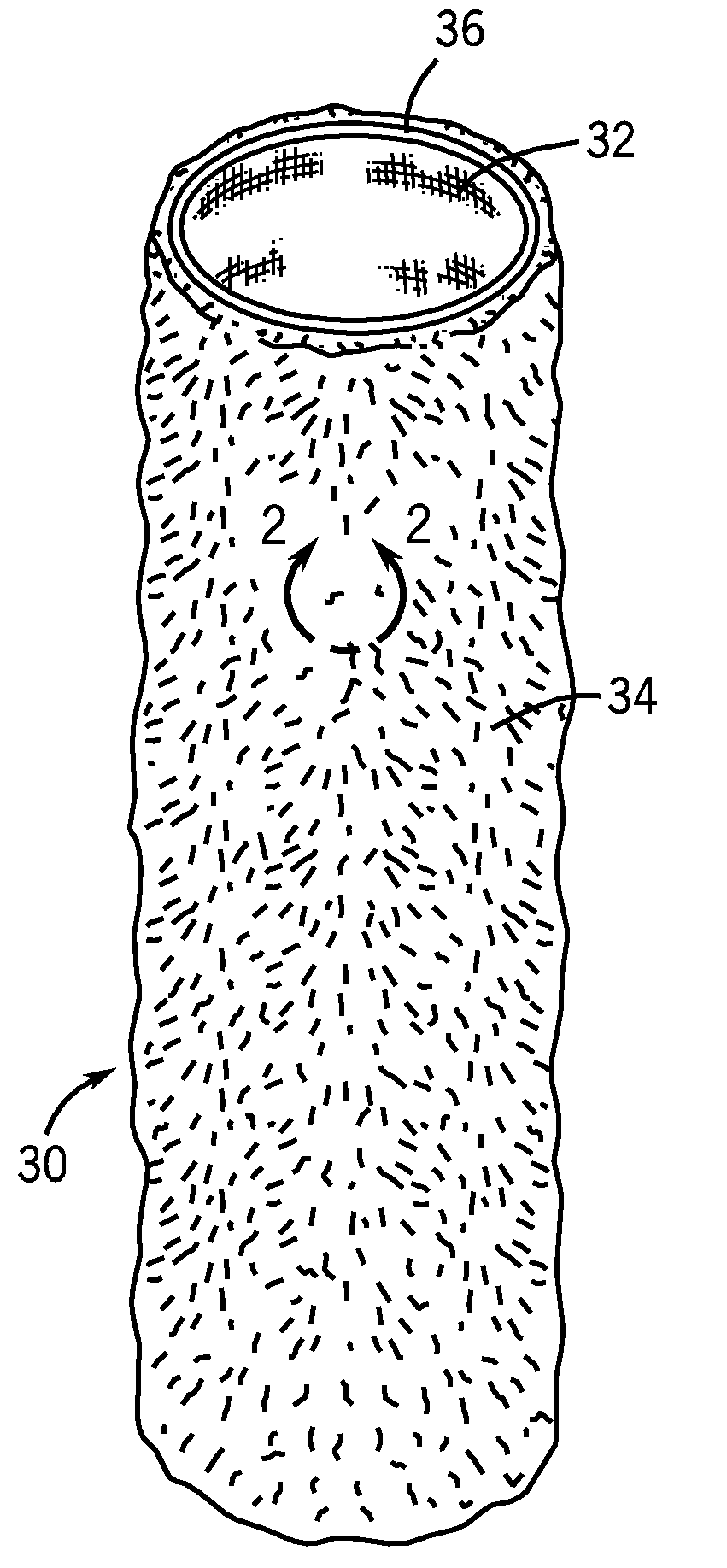
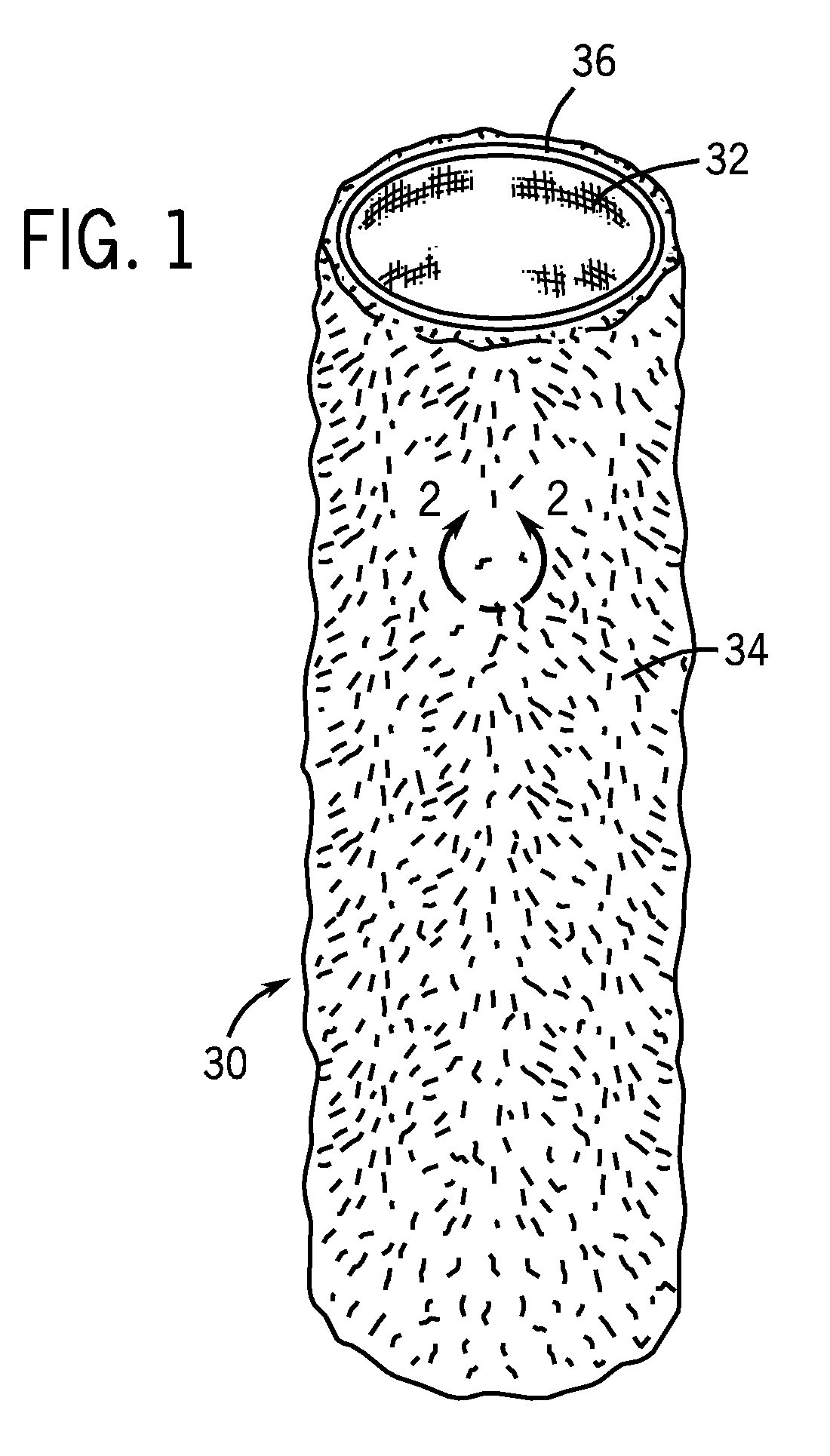
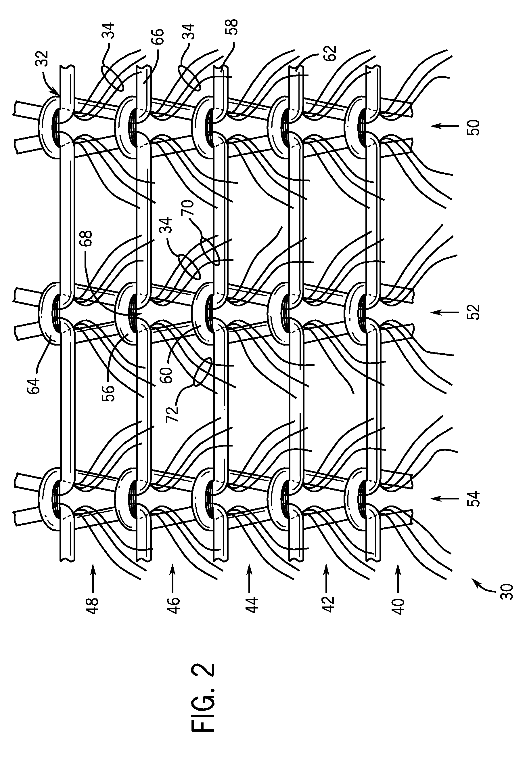
[0073]The paint roller cover manufacturing method of the present invention uses a tubular paint roller fabric that may be either a tubular knit base that is made of a low melt yarn having sliver pile fibers extending outwardly therefrom or a tubular knit base that is made of a low melt yarn having cut pile yarn segments extending outwardly therefrom. The former tubular paint roller fabric is discussed in detail in the above-incorporated by reference U.S. patent application Ser. No. 11 / 740,119 and is shown in FIGS. 1 and 2 herein, and the latter tubular paint roller fabric is discussed in detail in the above-incorporated by reference U.S. patent application Ser. No. 12 / 116,022 and is shown in FIGS. 3 and 4 herein.

[0074]Referring first to FIG. 1, a tubular sliver knit segment 30 that may be continuously knitted in an extended length is shown. The tubular sliver knit segment 30 consists of a knit backing or base material 32 having pile fibers 34 extending from the knit base material 32...


PUM

PropertyMeasurementUnit
temperatureaaaaaaaaaa

Abstract

A method of manufacturing paint roller covers is disclosed in which the paint roller covers are manufactured from a seamless, tubular fabric sleeve having a backing made at least in part from a material having a lower melting point than material used for the pile of the seamless, tubular fabric sleeve. The seamless, tubular fabric sleeve is placed onto a cylindrical member, and heat is applied to cause the material having the lower melting point in the backing be activated to cause the backing of the seamless, tubular fabric sleeve to remain in a cylindrical configuration. The activated tubular knitted pile fabric may be finished into paint roller covers by combing and shearing the pile fabric to a desired length, beveling the edges of the paint roller covers, and vacuuming stray fibers from the paint roller covers.

Description

IDENTIFICATION OF RELATED APPLICATION[0001]This patent application is a continuation-in-part of copending U.S. patent application Ser. No. 11 / 740,119, filed on Apr. 25, 2007, entitled “Tubular Sliver Knit Fabric for Paint Roller Covers,” and a continuation-in-part of copending U.S. patent application Ser. No. 12 / 015,612, filed on Jan. 17, 2008, entitled “Method of Manufacturing Paint Roller Covers From a Tubular Fabric Sleeve,” and a continuation-in-part of copending U.S. patent application Ser. No. 12 / 100,050, filed on Apr. 9, 2008, entitled “Method of Manufacturing Paint Roller Covers From a Tubular Fabric Sleeve,” and a continuation-in-part of copending U.S. patent application Ser. No. 12 / 116,022, filed on May 6, 2008, entitled “Tubular Cut Pile Knit Fabric for Paint Roller Covers,” all four of which patent applications are assigned to the assignee of the present invention, and all four of which patent applications are hereby incorporated herein by reference in their entirety.Fie...

Claims


Application Information

Patent Timeline
Patent Type & Authority Applications(United States)
IPC IPC(8): B29C51/42
CPCB05C17/0207B29L2023/22Y10T156/1052B29D23/001B29C2793/00B29L2031/328Y10T156/108
Inventor SINYKIN, DANIEL L.
Owner SEAMLESS TECH
Learn More