Laser System

a laser system and laser beam technology, applied in the field of laser beam systems, can solve the problems of unwanted nonlinear optical effects in the fibers, optical breakdown can occur before the beam reaches the fiber, and disadvantageous effects that increase with increasing power density, and achieve the effects of increasing power density, low beam divergence, and even further increase of output beams

Active Publication Date: 2008-10-30
FOTONA D D
View PDF5 Cites 3 Cited by
  • Summary
  • Abstract
  • Description
  • Claims
  • Application Information

AI Technical Summary

Benefits of technology

[0003]In spite of this, disadvantageous effects that increase with increasing power density can be observed for laser transmission within an articulated arm. At an appropriate power level of the laser beam, the air within the optical path can become ionized; this causes a deterioration of the beam profile at the output. At very high power densities, the ionization of air causes plasma generation that, in turn, leads to optical breakdown of the laser transmission. As soon as the plasma generation has been excited by a first part of the laser pulse, the remaining part of the laser pulse is absorbed to a large extent.
[0004]In addition, the optical components of the articulated arm are exposed to conditions very close to damage threshold. In the case of novel Q-switched laser designs employing variable reflectivity technology in combination with the unstable resonator concept, the brightness of the output beam is even further increased, contributing particularly to thermal loading of the optical components.
[0005]The main characteristics of the beam emerging from such a laser are exceptional uniformity of the near-field beam profile and very low beam divergence so that, in this way, diffraction-limited conditions are approached. The uniform top hat profile is one of the most desirable profiles for many applications since it offers unique light-to-matter interaction conditions across the whole beam area. However, due to the high quality of the beam in terms of the M2 parameter, any change in laser resonator conditions, in particular variations related to the laser rod lensing due to different pumping conditions, result in accentuated variations of the beam farther away from the laser output. Not only the beam diameter is influenced in this way but the beam profile quality also deteriorates in comparison to highly desired near-field top hat conditions; this is usually unacceptable for laser applications.
[0006]To solve the problem to some extent, it is possible to trigger the laser flash-lamp at the highest repetition rate, and, by periodically activating the Q-switch cell, lower repetition rates can be obtained also. This kind of laser operation has many drawbacks. The laser pumping chamber operates at full pumping power most of the time, and this worsens problems concerning thermal load of the laser rod and related optical properties. Additionally, the lifetime of the flash-lamps is affected in this way and the overall electrical power consumption increases.
[0007]In order to solve the problems described above, an optical arrangement of the articulated arm may be considered that is based on the imaging of the plane of invariant beam profile onto the target plane. Such an optical arrangement is based on the fact that the beam change close to the laser output mirror is small and virtually does not change with the variation of the pumping conditions. This is particularly true in the case of unstable laser resonator concept with variable reflectivity output mirrors that can be optimized in such a way that beam profile propagation characteristics very close to the plane wave diffraction on a circular aperture are produced. The beam profile in the vicinity of the laser output is therefore close to top hat shape, and changes of beam diameter due to different lensing properties of the laser rod are small. Such an imaging of the plane of invariant beam profile onto the target plane is proposed in WO 01 / 78633 A2.
[0008]However, WO 01 / 78633 A2 does not teach in detail how imaging can be performed to achieve the desired goal. The optical arrangement of a high power laser system is usually designed in a way to maintain a reasonably large beam diameter throughout the beam path in the system. This approach reduces loading of the optical components and ionization of the air, but leads to a poor imaging quality.

Problems solved by technology

When focusing a high power laser beam into a fiber, optical breakdown can occur before the beam reaches the fiber.
In addition, unwanted nonlinear optical effects occur in the fibers.
In spite of this, disadvantageous effects that increase with increasing power density can be observed for laser transmission within an articulated arm.
At an appropriate power level of the laser beam, the air within the optical path can become ionized; this causes a deterioration of the beam profile at the output.
At very high power densities, the ionization of air causes plasma generation that, in turn, leads to optical breakdown of the laser transmission.
In addition, the optical components of the articulated arm are exposed to conditions very close to damage threshold.
In the case of novel Q-switched laser designs employing variable reflectivity technology in combination with the unstable resonator concept, the brightness of the output beam is even further increased, contributing particularly to thermal loading of the optical components.
Not only the beam diameter is influenced in this way but the beam profile quality also deteriorates in comparison to highly desired near-field top hat conditions; this is usually unacceptable for laser applications.
The laser pumping chamber operates at full pumping power most of the time, and this worsens problems concerning thermal load of the laser rod and related optical properties.
Additionally, the lifetime of the flash-lamps is affected in this way and the overall electrical power consumption increases.
However, WO 01 / 78633 A2 does not teach in detail how imaging can be performed to achieve the desired goal.
This approach reduces loading of the optical components and ionization of the air, but leads to a poor imaging quality.

Method used


Image

  • Laser System
  • Laser System
  • Laser System

Examples


Embodiment Construction

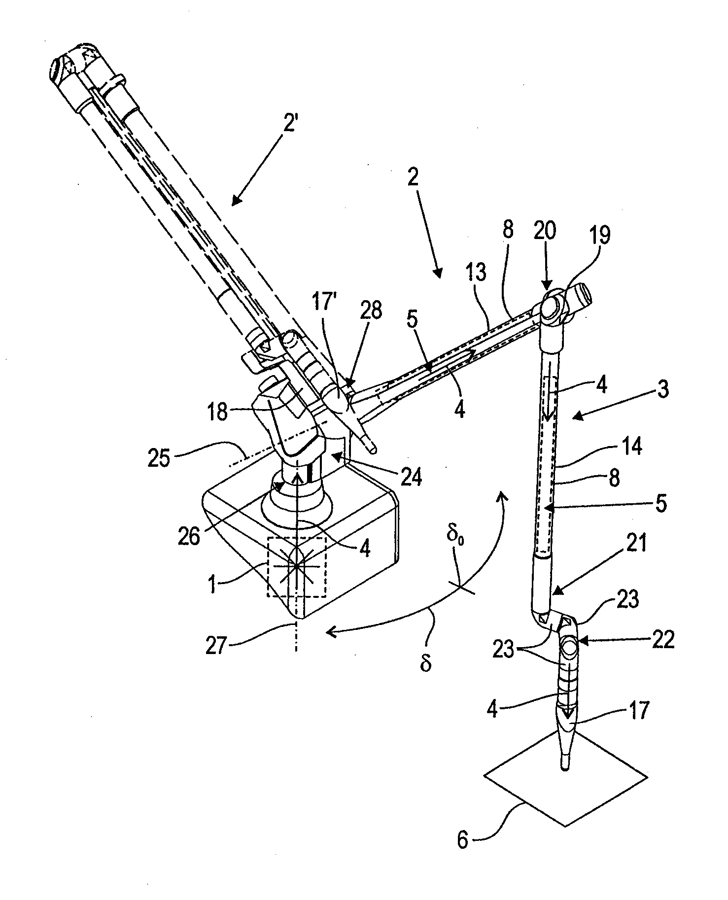
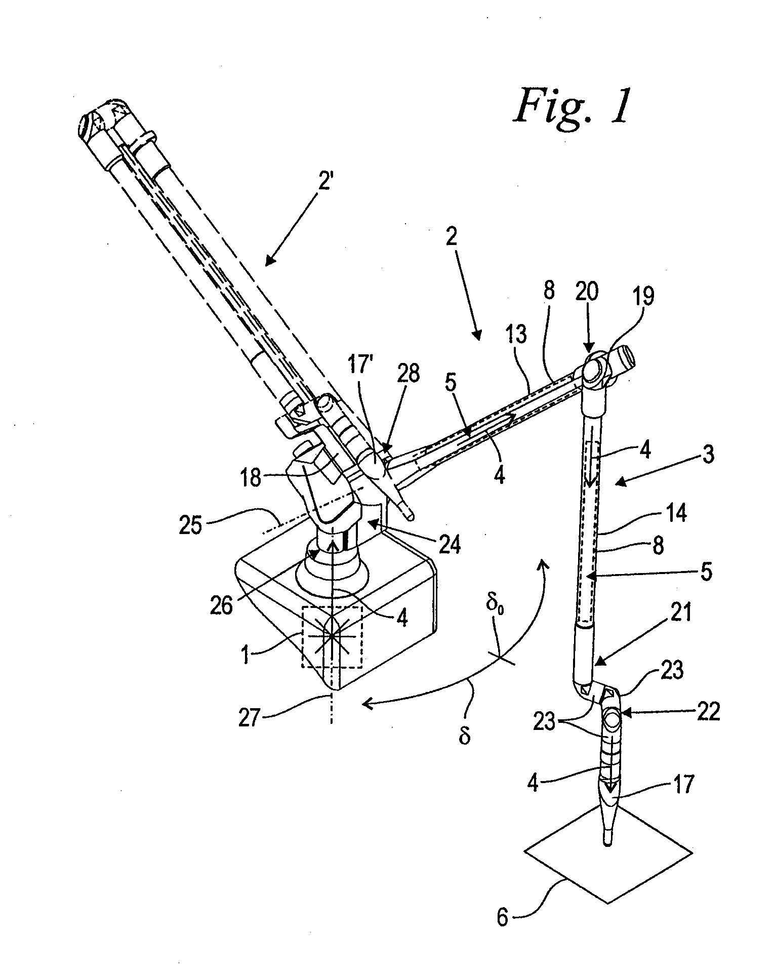
[0028]FIG. 1 shows in a perspective view a laser system embodied in accordance with the invention, comprising a laser source 1 and a manually guided articulated arm 2. The articulated arm 2 comprises a stationary support 24 that is pivotable by means of a pivot joint 26 about a vertical pivot axis 27; a first arm section 13 and a second arm section 14; an articulated arm section 22; and a hand piece 17. The first arm section 13 is supported by means of a pivot joint 28 with a horizontal pivot axis 25 on the stationary support 24. On the free end 20 of the first arm section 13 positioned opposite the pivot joint 28, an additional pivot joint 19 is provided with which the second arm section 14 is pivotably supported on the first arm section 13. In the area of the free end 21 of the second arm section 14, the hand piece 17 is arranged. Between the free end 21 of the second arm section 14 and the hand piece 17, the articulated arm section 22 is arranged that comprises at least two, in t...


PUM

PropertyMeasurementUnit
pressureaaaaaaaaaa
pressureaaaaaaaaaa
pressureaaaaaaaaaa

Abstract

The invention relates to laser system with a laser source and an articulated arm. The articulated arm has an optical arrangement for guiding a laser beam from the laser source along an optical path in the articulated arm to a target location. Within the optical path at least one crossing area (focus or focal point) of the laser beam is provided. The optical arrangement has at least one optical cell with an input window and an output window for passing the laser beam therethrough, wherein the crossing area is positioned within the optical cell. The optical cell has a gas fill with an energy threshold for ionization that is increased in comparison to that of ambient air.

Description

BACKGROUND OF THE INVENTION[0001]The invention relates to a laser system comprising a laser source and an articulated arm; wherein the articulated arm comprises an optical arrangement for guiding a laser beam from the laser source along an optical path within the articulated arm to a target location.[0002]In technical and particularly in medical applications, the transmission of a laser beam from a laser source to a target location is realized either by a flexible light guide or along an optical path within an articulated arm. In the case of high-power lasers, the articulated arm is preferred for a couple of reasons: Fibers cannot withstand high optical power densities. When focusing a high power laser beam into a fiber, optical breakdown can occur before the beam reaches the fiber. In addition, unwanted nonlinear optical effects occur in the fibers.[0003]In spite of this, disadvantageous effects that increase with increasing power density can be observed for laser transmission with...

Claims


Application Information

Patent Timeline
Patent Type & Authority Applications(United States)
IPC IPC(8): H01S3/08
CPCA61B18/201B23K26/0643B23K26/0648B23K26/0665B23K26/0884B23K26/428H01S3/005H01S3/08059H01S3/08081B23K26/707
Inventor MARINCEK, MARKOCENCIC, BORIS
Owner FOTONA D D
Why Eureka
Try Eureka