Optical devices and related systems and methods

Inactive Publication Date: 2008-11-06
CARL ZEISS SMT GMBH
View PDF18 Cites 4 Cited by
  • Summary
  • Abstract
  • Description
  • Claims
  • Application Information

AI Technical Summary

Benefits of technology

[0006]In some embodiments, the light beam intensity non-uniformity correction device includes an optical element having a light entrance face with a certain antireflective property. The antireflective property is locally amended in such a mann

Problems solved by technology

In an optical system, consisting of a plurality of optical elements (as is the case for a laser annealing apparatus for carrying out such crysta

Method used


Image

  • Optical devices and related systems and methods
  • Optical devices and related systems and methods
  • Optical devices and related systems and methods

Examples


Example

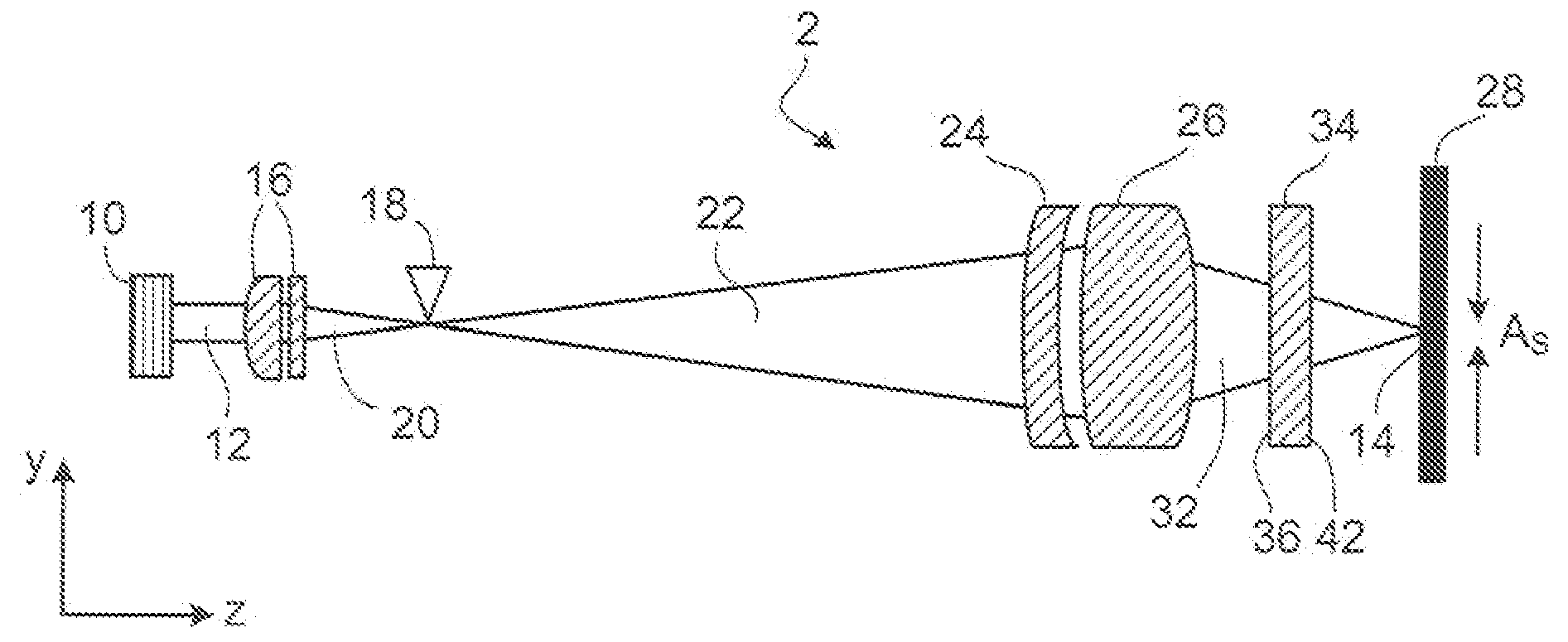
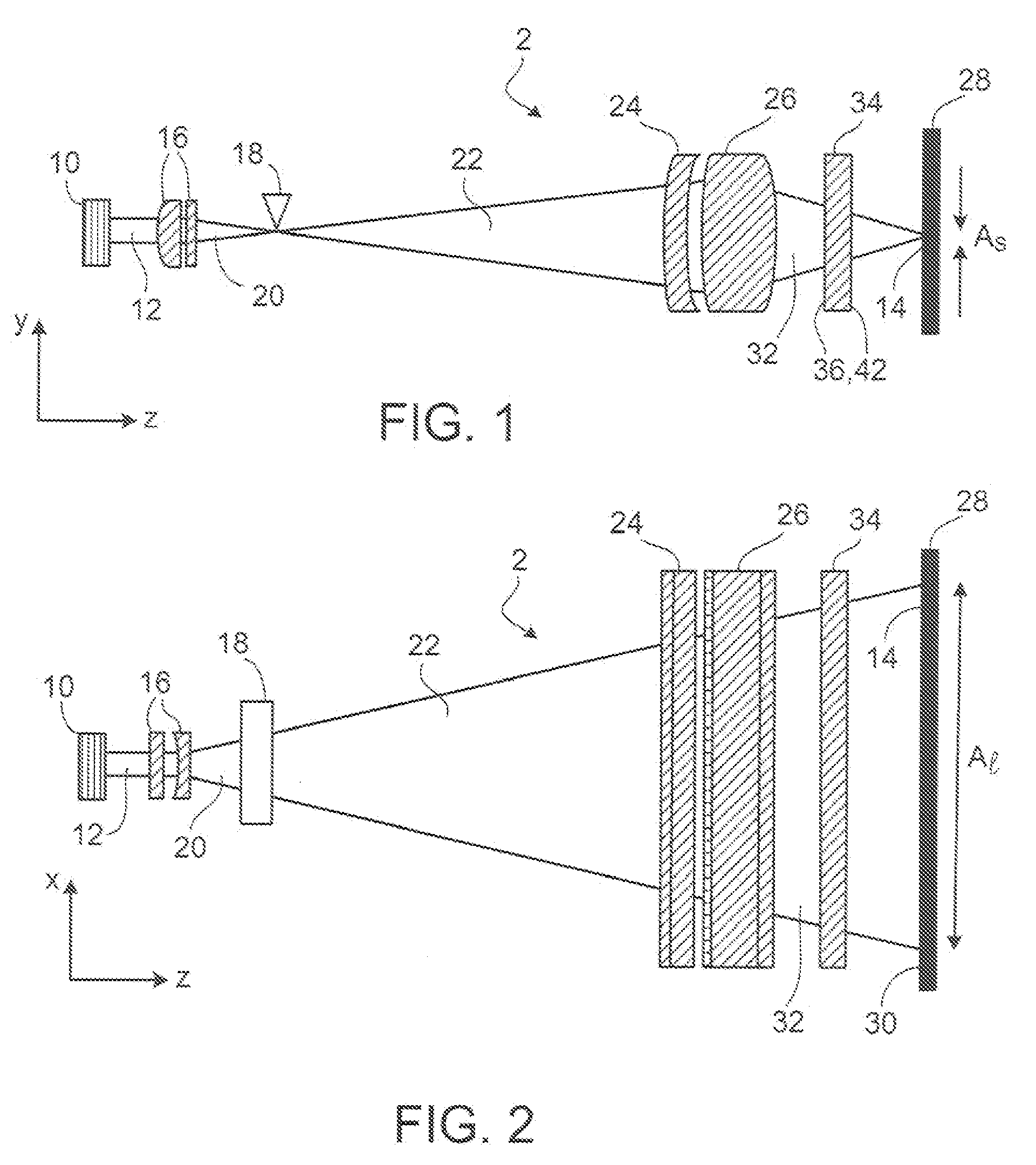
[0070]The description includes an anamorphic optical system which is capable for laser crystallization of an amorphous silicon layer.

[0071]Such an optical system is illustrated in FIGS. 1 and 2 and therein marked with the reference number 2. This optical system 2 comprises an excimer laser 10 which emits a pulsed beam 12 in per se known manner in z-direction. The dimensions of the excimer laser beam 12 emitted, for instance, may be 15 times 40 mm (in the xy-plane). The excimer laser 10 may preferably emit radiation in the spectral range between 130 nm and 390 nm. Instead of an excimer laser also a pulsed CO2-laser, a diode laser, a solid state laser or a frequency doubled solid state laser may be used.

[0072]This laser beam is imaged by means of the optical system 2 which will be specified below to yield an illuminating line 14 in a field plane 30.

[0073]The laser beam 12 emitted by the excimer laser 10 first passes an attenuator (not shown), if desired, and then enters a set of anamo...


PUM

PropertyMeasurementUnit
Thicknessaaaaaaaaaa
Surfaceaaaaaaaaaa
Antireflectiveaaaaaaaaaa

Abstract

The disclosure relates to a light beam intensity non-uniformity correction device that includes an optical element having a light entrance face with an antireflective property. According to the invention the antireflective property is locally amended in order to enhance light beam intensity uniformity. The disclosure further relates to a method for amending intensity distribution of a light beam in an optical system having one or more optical elements, where the method includes: a) assembling the optical system with the one or more optical elements arranged in predetermined positions, b) measuring intensity distribution, c) calculating locally required increase or decrease in absorption and/or reflection of one of the optical elements to amend measured intensity distribution into a predetermined intensity distribution, d) removing the optical element from the optical system, e) locally amending absorption and/or reflection of the one of the optical elements according to the calculation, f) installing the optical element in the predetermined position in the optical system.

Description

CROSS-REFERENCE TO RELATED APPLICATION[0001]This application claims the benefit under 35 U.S.C. § 119(e)(1) of U.S. Provisional Application No. 60 / 731,313, filed Oct. 28, 2005, the contents of which are hereby incorporated by reference.FIELD[0002]The disclosure relates to a light beam intensity non-uniformity correction device that includes an optical element having a light entrance face with an antireflective property. The optical element can have at least one face covered with an anti-reflective coating. The disclosure further relates to a method for amending intensity distribution of a light beam in an optical system having one or more optical elements. The method can correct light beam intensity non-uniformity. The disclosure also relates to an anamorphic optical system for generating a sharp illuminating line on a surface, where the illuminating line can have a high aspect ratio and a cross-section with long and short axes. The disclosure relates to a scanning system for produc...

Claims


Application Information

Patent Timeline
IPC IPC(8): G01J1/32
CPCG02B1/115G02B5/22G02B13/08G03F7/70975G02B27/0988G03F7/70591G03F7/70958G02B27/0966G02B1/11G02B27/00G03F7/20
Inventor SHKLOVER, VITALIYKIEREY, HOLGERMUENZ, HOLGERLE MAIRE, MICHELWEIGL, BERNHARD
Owner CARL ZEISS SMT GMBH
Why Eureka
Try Eureka