Methods and apparatus for reducing artifacts in computed tomography images

a computed tomography and computed tomography technology, applied in material analysis using wave/particle radiation, instruments, nuclear engineering, etc., can solve the problems of blurred local variations in density that are not supported by projection data, less projection data, and less accurate ray sums. , to achieve the effect of suppressing edge artifacts and good images

Inactive Publication Date: 2008-11-06
BOAS FRANZ EDWARD
View PDF7 Cites 43 Cited by
  • Summary
  • Abstract
  • Description
  • Claims
  • Application Information

AI Technical Summary

Benefits of technology

[0007]In one embodiment of the present invention, we start with an initial estimate of the CT image, which can be generated by an existing CT reconstruction method. This initial estimate is then iteratively corrected to reduce artifacts. In each iteration, constraints such as non-negativity of X-ray attenuation coefficients, may be applied first. Next, the image is blurred to guide convergence to a smoother image with fewer artifacts. Finally, the image is modified using an algebraic reconstruction algorithm to try to match the projection data to within the experimental error. Notice that the final image is not blurred, because the correction step ensures that the image is still consistent with the projection data. However, any local variations in density that are not supported by the projection data are blurred out.
[0008]In the embodiment described in the previous paragraph, the entire image is updated in each iteration. In a variation on this embodiment, a mask is calculated for each iteration which specifies which parts of the image will be updated on that iteration. The use of a mask allows us to first solve regions of the image that are determined by rays with low photon counts (and thus high error). Then, regions of the image determined by rays with higher photon counts (and thus lower error), are solved using those ray sums.
[0009]This invention addresses the major sources of artifacts in CT images. Poisson counting error (shot noise) is directly incorporated into the experimental error model. Scatter and beam-hardening effects can be treated by pre-processing the projection data. Any remaining errors can then be incorporated into the experimental error model. Even if the experimental error model is wrong, the use of a mask allows data from rays with high photon counts to override data from rays with low photon counts. The mask also allows data from rays away from an edge to override data from rays near an edge, thus suppressing edge artifacts. Finally, the blurring step allows the method to pick a smooth image, out of the large set of images consistent with the projection data. Thus, good images can be obtained even for very fast scans that generate less projection data than necessary to uniquely specify an image.

Problems solved by technology

First, ray sums corresponding to fewer photon counts are less accurate, so the reconstruction method should not try to match these ray sums as closely.
However, any local variations in density that are not supported by the projection data are blurred out.

Method used


Image

  • Methods and apparatus for reducing artifacts in computed tomography images
  • Methods and apparatus for reducing artifacts in computed tomography images
  • Methods and apparatus for reducing artifacts in computed tomography images

Examples


Embodiment Construction

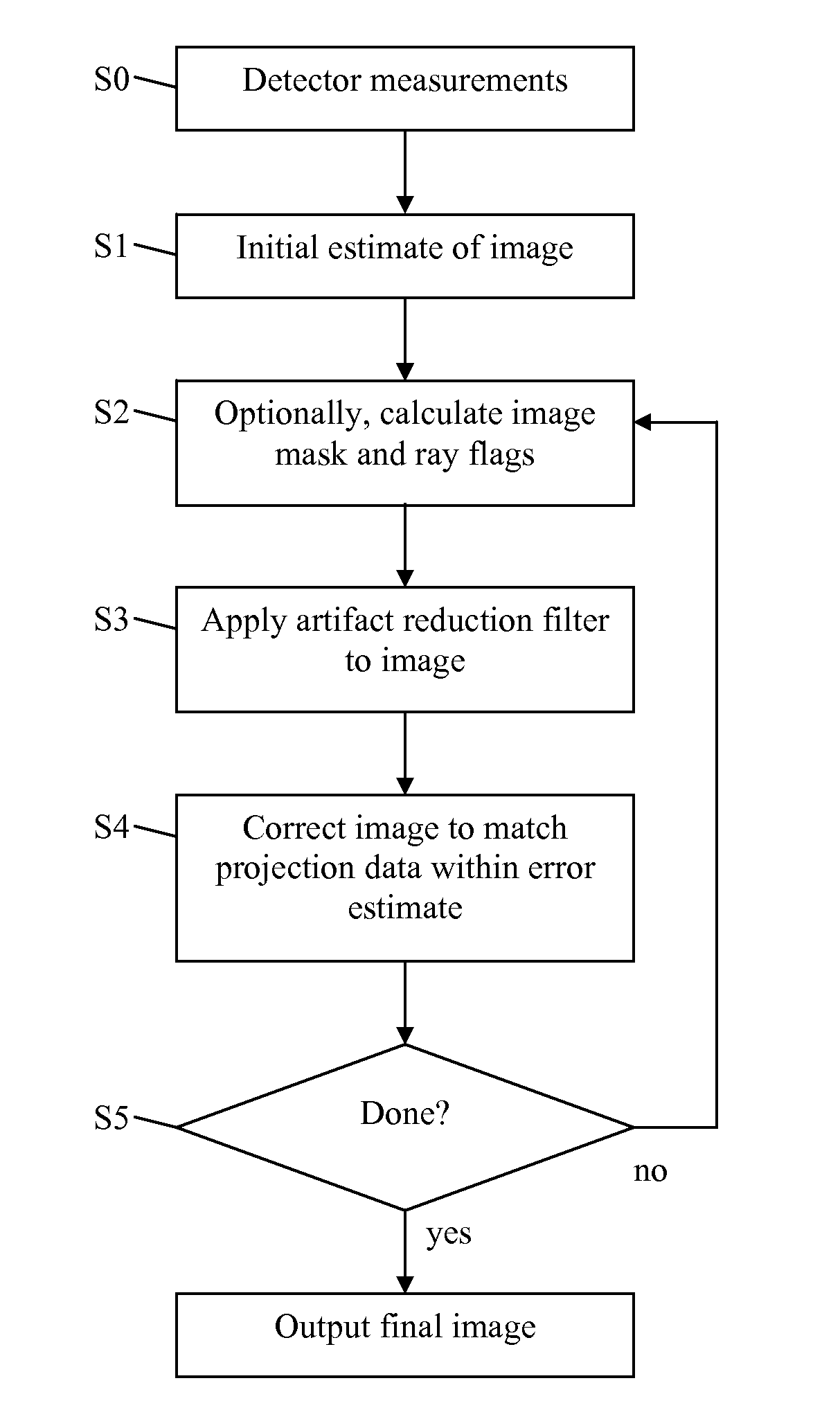
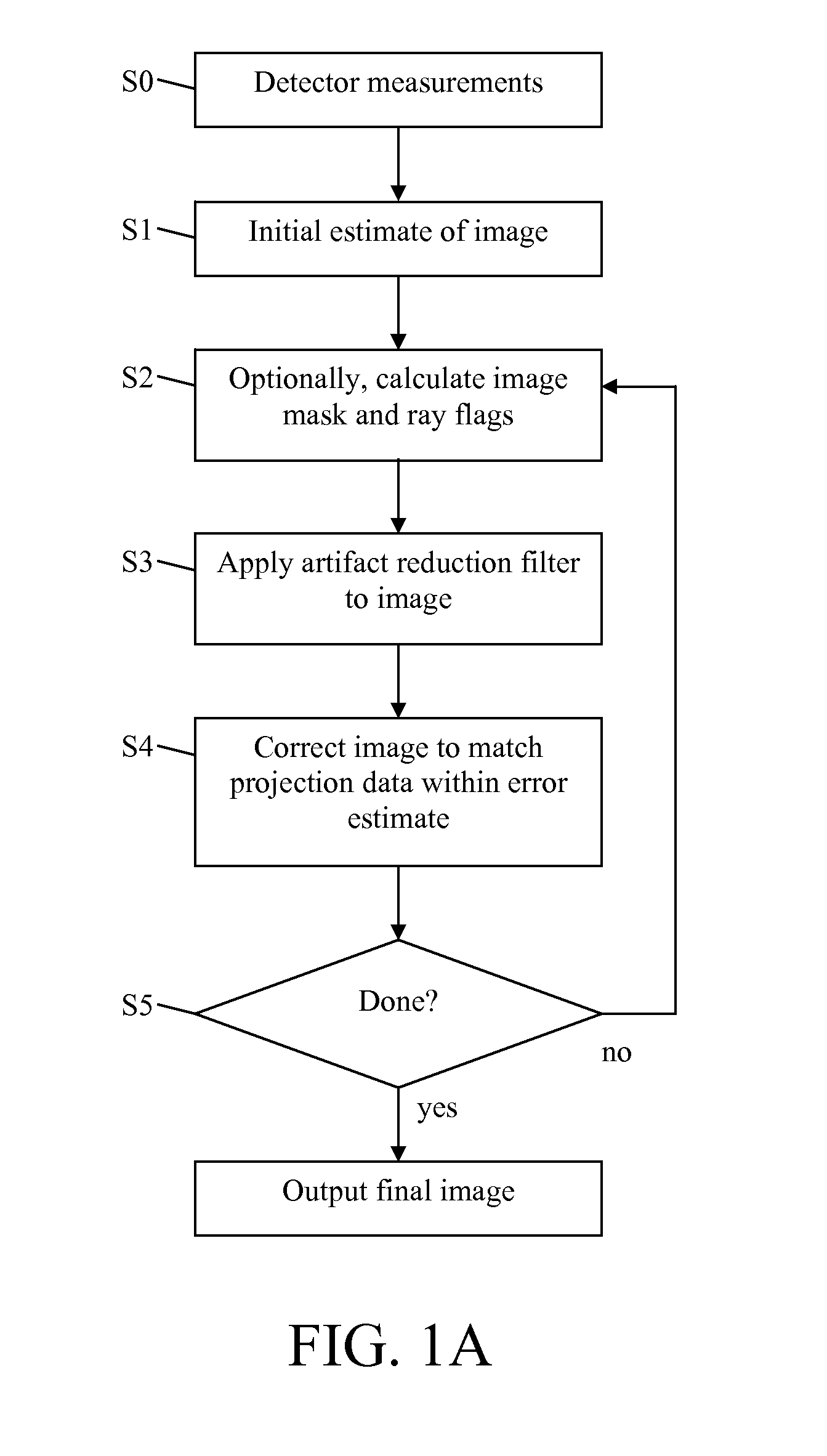
[0014]A flowchart showing one embodiment is illustrated in FIG. 1A and described in detail below.

[0015]Step S0. Projection data are obtained from a plurality of detectors configured to detect transmitted, emitted, or reflected photons, other particles, or other types of radiated energy. These measurements are made by a CT, PET, SPECT, or other type of scanner.

[0016]Step S1. The projection data can be pre-processed to account for beam-hardening, scatter, refraction, diffraction, or other phenomena. Furthermore, low photon counts from nearby rays can be averaged together to reduce the error. The projection data can be interpolated to generate a higher resolution data set. The projection data can be filtered to account for cross-talk between the detectors, or to reduce noise. Many other pre-processing techniques are known to those in the art.

[0017]The initial estimate of the CT image is then generated by an existing CT reconstruction method, such as filtered backprojection. The artifac...


PUM

PropertyMeasurementUnit
densityaaaaaaaaaa
densitiesaaaaaaaaaa
CT reconstructionaaaaaaaaaa

Abstract

We present an iterative method for reducing artifacts in computed tomography (CT) images. In each iteration, constraints such as non-negativity are applied, then the image is blurred to guide convergence to a smoother image. Next, the image is modified using an algebraic reconstruction algorithm to try to match the projection data to within the experimental error. A mask is calculated which specifies which parts of the image to update during each iteration. The mask allows us to first solve regions of the image that are determined by rays with low photon counts (and thus high error). Then, regions of the image determined by rays with higher photon counts (and thus lower error), are solved using those ray sums. Reducing CT scan artifacts results in clearer and higher resolution images, faster scan times, and less radiation use.

Description

BACKGROUND OF THE INVENTION[0001]A computed tomography (CT) scanner uses X-rays to determine the three-dimensional structure of an object. X-ray beams (“rays”) are passed through the object from different angles, and detectors on the other side measure the intensity of each attenuated ray. Here, “ray” refers to the path traversed by X-rays between the source and a single detector. All of the detector measurements for a single fixed X-ray source and detector configuration are referred to as a “projection.” The complete set of projections (“projection data”) can also be expressed as “ray sums,” which provide information on the sum of the X-ray attenuation coefficients along each ray. “Ray sums” can also be obtained using other imaging modalities, such as positron emission tomography (PET), or single photon emission computed tomography (SPECT). For these other imaging modalities, “ray sum” refers to the sum of the emitter densities along a given path. The ray sums are then reconstructe...

Claims


Application Information

Patent Timeline
Patent Type & Authority Applications(United States)
IPC IPC(8): G01N23/00G06K9/40
CPCG06T11/005G06T2211/424
Inventor BOAS, FRANZ EDWARD
Owner BOAS FRANZ EDWARD
Why Eureka
Try Eureka