
Anodizing Aluminum and Alloys Thereof

anodizing aluminum and alloys technology, applied in the direction of electrolytic coatings, magnetic materials, electrical equipment, etc., can solve the problems of reducing the fatigue strength of aluminum, pvd process may not provide desirable color choices, and painting and lacquering are generally not durable,

Inactive Publication Date: 2008-11-06
DURACOUCHE INT
View PDF9 Cites 109 Cited by
  • Summary
  • Abstract
  • Description
  • Claims
  • Application Information

AI Technical Summary

Benefits of technology

[0014](b) anodizing the aluminum material with a first current having a density of less than 0.5 A/dm2 for a time period from about 1...

Problems solved by technology

For example, painting and lacquering are generally not durable and may fail to comply with the Restriction of Hazardous Substances Directive (RoHS) adopted by the European Union for restricting heavy metals and toxic substances.
On the other hand, the PVD process may not provide desirable color choices in some instances, as well as the required process stability in mass production.
Chromic anodizing may also reduce the fatigue strength of the aluminum less than the other methods described herein.
Although the anodizing processes offer advantages over other techniques and can provide decorative oxide layers having one or more colors with or without dyeing, the anodizing processes, such as the Type II and Type III processes, suffer from some drawbacks.
For example, the Type III anodizing process generally provides hard and opaque oxide layers that may be difficult to be dyed and polished.
Further, the Type II anodizing process, may not generate an oxide layer hard and / or shinny enough for some decorative coating applications.
Further, the Type II anodic oxide layer can dissolve in the corrosive anodizing bath so that the thickness of the Type II oxide layer may be limited.
Even though the corrosion may not be significant in thicker workpieces, the corrosion can still roughen the surfaces and generate surface defects, such as flow marks, teardrops, etched trenches and the like, in the oxide layer.

Method used


Image

  • Anodizing Aluminum and Alloys Thereof
  • Anodizing Aluminum and Alloys Thereof

Examples


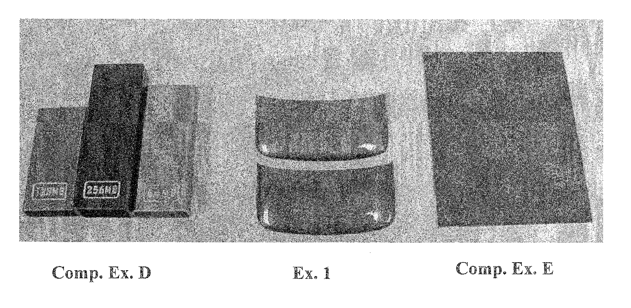
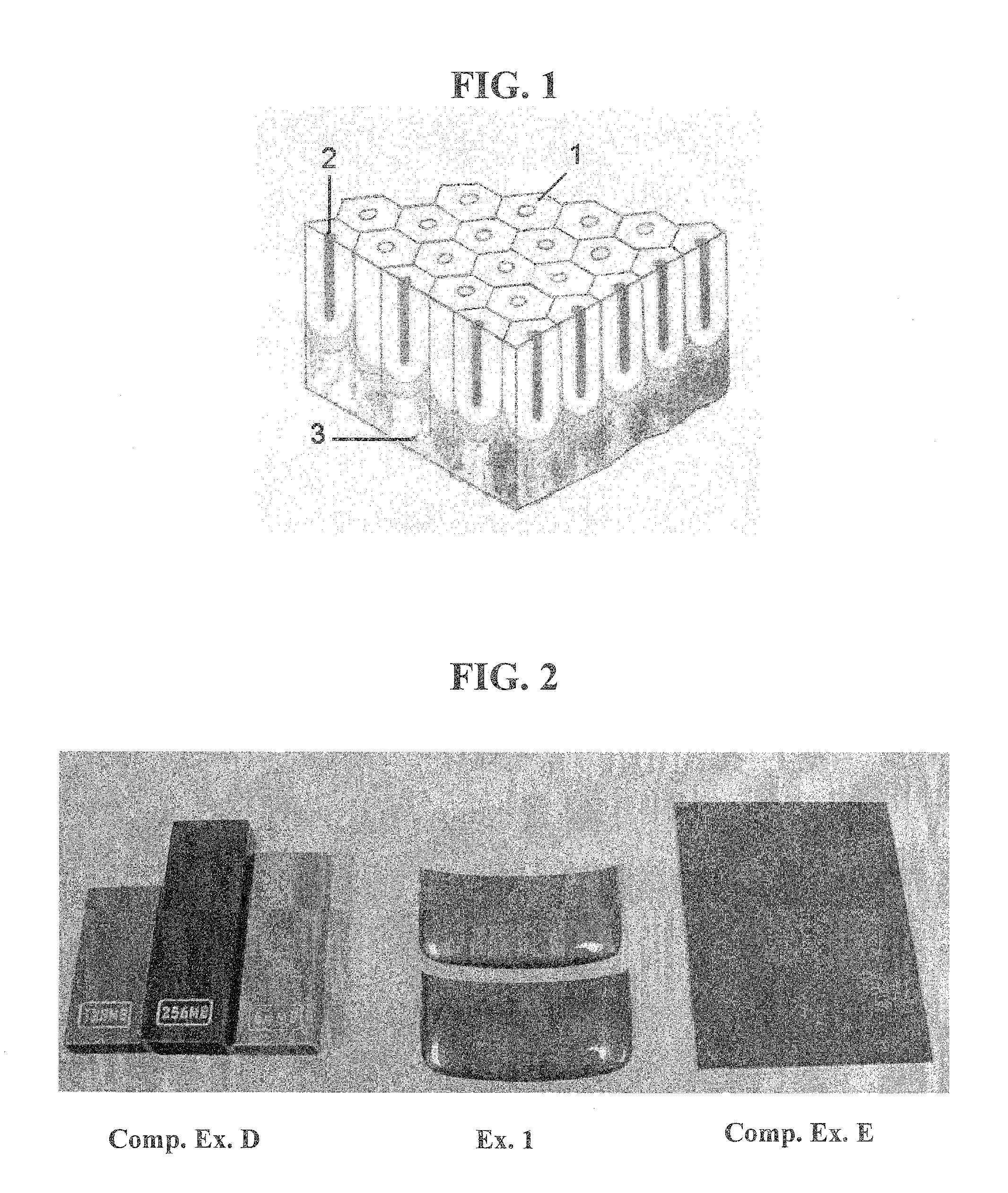
example 1

[0113]Example 1 was prepared by anodizing an aluminum alloy Al-6063 workpiece in an electrolyte bath comprising water, sulfuric acid (180 g / liter of electrolyte) and oxalic acid (16 g / liter of electrolyte) at a temperature from about 10° C. to about 16° C. The anodizing process were done in four sequential steps, each of which involved a different current density and electrolysis time. The current density of the first step was from 0 to about 0.7 A / dm2 for 10 minutes. The current density of the second step was from 0.7 A / dm2 to about 2.0 A / dm2 for 10 minutes. The current density of the third step was from 2.0 A / dm2 to about 2.5 A / dm2 for 10 minutes. The current density of the fourth step was from 1.5 A / dm2 to about 2.5 A / dm2 for 50 minutes. The current densities were generated by a pulse type DC having a voltage potential from about 20 V to about 24 V. The sequence of the first, second and third pulse currents was 0.8 seconds on and then 0.2 seconds off. The sequence of the fourth p...

example 2

[0114]Example 2 was prepared similarly according to the procedure for Example 2 except that the workpiece was dyed with a blue color.

example 3

[0115]Example 3 was prepared similarly according to the procedure for Example 2 except that the workpiece was dyed with a red color


PUM

PropertyMeasurementUnit
Temperatureaaaaaaaaaa

Abstract

This invention encompasses methods of producing a colored oxide layer on an aluminum material by anodizing the aluminum material in an electrolyte comprising water, sulfuric acid and oxalic acid. The anodizing step comprises passing at least two sequential current densities through the electrolyte. Methods of making and using article with a colored oxide layer on an aluminum material make by the methods disclosed herein are also disclosed.

Description

FIELD OF THE INVENTION[0001]This invention encompasses methods of producing a colored oxide layer on an aluminum material. In particular, this invention encompasses methods of producing a colored oxide layer by anodizing an aluminum material in an electrolyte comprising sulfuric acid and oxalic acid.BACKGROUND OF THE INVENTION[0002]Aluminum and its alloys are known for their desirable properties such as light weight, strength, durability and fabrication flexibility. In 1889, Alcoa, Inc. was granted a patent (i.e., U.S. Pat. No. 400,664) for an electrolytic process of making aluminum from aluminum oxide, which substantially lowered the cost of making aluminum. Since then, because of their desirable properties and low costs, aluminum and its alloys have been widely used in many industries such as aerospace, transportation, building, semiconductor and electronic. As a result, the global use of aluminum exceeds that of any other metal except iron in terms of both quantity and value.[000...

Claims


Application Information

Patent Timeline
IPC IPC(8): C25D11/12B32B15/00C25D11/18C25D21/10
CPCC25D11/08Y10T428/12993Y10T428/12C25D11/024C25D11/04
Inventor NG, FUK CHIULI, SHU CHUNG
Owner DURACOUCHE INT
Learn More