

Process For Sequestrating Carbon In The Form Of A Mineral In Which The Carbon Has Oxidation Number +3
a technology of carbon sequestration and mineralization, applied in the field of electrochemical reduction of co2, can solve the problem of uncertain durability of such storage facilities over very long periods
- Summary
- Abstract
- Description
- Claims
- Application Information
AI Technical Summary
Benefits of technology
Problems solved by technology
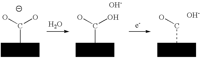
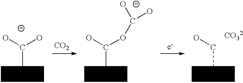
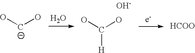
Method used
Image

Examples
example 1
[0036]Liquid CO2 was obtained by a conventional liquefaction process.
[0037]The reactor was filled with CO2 liquid under pressure (50 bars at ambient temperature) and steadily supplemented with water to maintain the CO2 / H2O molar ratio to about 100 to orientate the reaction towards the synthesis of oxalic acid. Tetra-ammonium perchlorate was added in an amount of 0.1 mol / l.
[0038]The electrode was platinum and the current density was 5 mA / cm2. The electrode potential was −3 V with respect to the potential of the Fe / Fe+ couple. The solution was stirred to limit concentration effects at the electrodes.
[0039]The quantity of CO2 to be electro-reduced fixed the quantity of electricity required.
[0040]After electro-reduction, the oxalic acid formed was injected into a receptacle containing calcium carbonate. The oxalic acid reacted with the carbonate to form a calcium oxalate. The increase in mass of the dried and cleaned residue demonstrated the sequestration of CO2 in the mineral form.
example 2
[0041]Liquid CO2 was obtained by a conventional liquefaction process.
[0042]It was supplemented with tetra-ammonium perchlorate and injected into a subterranean cavity containing calciferous or magnesia-containing rocks. Electro-reduction was carried out directly in the cavity using a platinum electrode. The current density was 5 mA / cm2. The electrode potential was −3 V with respect to the potential of the Fe / Fe+ couple. The solution was stirred to limit concentration effects at the electrodes.
[0043]The synthesized oxalic acid reacted with the calciferous or magnesia-containing rocks liberating CO2, which was also reduced, and a divalent cation which precipitated with the oxalate. The reactions finally resulted in the sequestration of CO2 by a mineral pathway. The CO2 liberated was recycled to the liquefaction step.
example 3
[0044]CO2 was absorbed with water in the presence of carbonic anhydrase as described in U.S. Pat. No. 6,524,843.
[0045]Tetra-ammonium perchlorate was added in an amount of 0.1 mol / l.
[0046]The electrode was platinum and the current density was 5 mA / cm2. The electrode potential was −3 V with respect to the potential of the Fe / Fe+ couple. The solution was stirred to limit concentration effects at the electrodes.
[0047]The quantity of CO2 to be electro-reduced fixed the quantity of electricity required.
[0048]After electro-reduction, the formic acid formed was injected into a receptacle containing calcium carbonate. The formic acid reacted with the carbonate to form a calcium formate. The increase in mass of the dried and cleaned residue demonstrated the sequestration of CO2 in the mineral form.
PUM
| Property | Measurement | Unit |
|---|---|---|
| Electric potential / voltage | aaaaa | aaaaa |
| Pressure | aaaaa | aaaaa |
| Concentration | aaaaa | aaaaa |
Abstract
Description
Claims
Application Information