High Strength Spring Steel and Steel Wire

Active Publication Date: 2008-11-13
NIPPON STEEL CORP
View PDF5 Cites 26 Cited by
  • Summary
  • Abstract
  • Description
  • Claims
  • Application Information

AI Technical Summary

Benefits of technology

[0016]The present invention gives spring steel controlling the oxides and sulfides in the steel, something never noted in conventional spring steel wire, by chemical elements so as to achieve both high strength and coilability. Further, the present invention does not just take note of the

Problems solved by technology

However, if the spring-use steel wire for cold coiling increases in strength, it will break at the time of cold coiling and will be unable to be formed into a spring shape in many cases.
In this case, both strength and workability cannot be achieved, so the wire has to be coiled by industrially disadvantageous methods.
Such heating at the time of coiling and thermal refining after coiling become causes of variations in spring dimensions due to heat treatment and result in a sharp drop in the processing efficiency, so the resultant springs are inferior to cold coiled springs in respect to cost, precision, and product stability.
These show that control of the average grain size of the V- and Nb-based carbides alone is insufficient (for example, see Japanese Patent Publication (A) No. 10-251804).
In this prior art, it is described that there is a concern over the formation of a

Method used


Image

  • High Strength Spring Steel and Steel Wire
  • High Strength Spring Steel and Steel Wire
  • High Strength Spring Steel and Steel Wire

Examples


example 1

[0165]Tables 1 to 3 show the ingredients of the steel materials prepared for evaluating the various types of performance, while Tables 4 to 6 show the methods of melting, properties, etc. of the steel materials. The steel materials were melted in small vacuum melting furnaces (either of 10 kg, 150 kg, or 2 ton) and further a 270 ton converter. The furnaces used for melting in the examples are shown. In the case of melting in a vacuum melting furnace, a magnesia crucible is used and otherwise sufficient care is taken regarding the entry of oxide producing elements from refractories and materials. The ingredients are adjusted to give the same composition as an actual converter melted material.

[0166]Among these small amounts of melted samples, the 150 kg material was welded to a dummy billet and rolled. Further, the 10 kg melted material was forged to φ13, then heat treated (normalized), and machined (φ10 mm×400 mm) in that order to prepare a thin straight rod. At this stage, the distr...

example 2

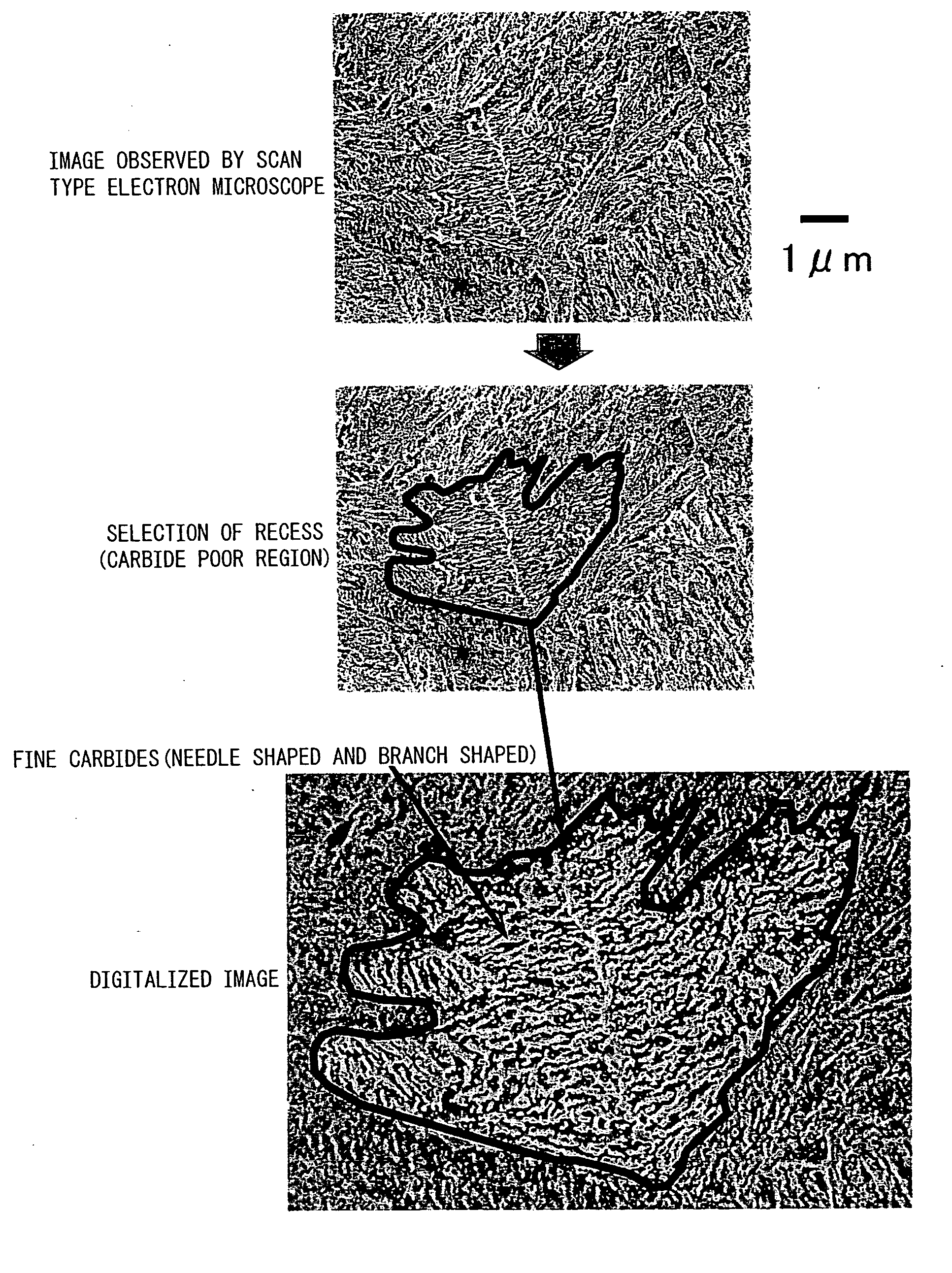
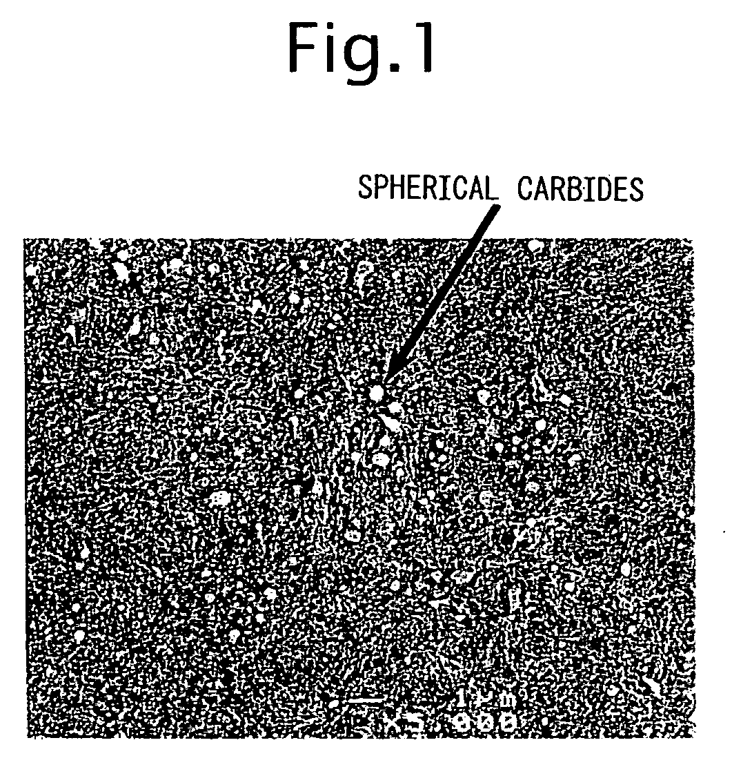
[0189]The chemical ingredients of the present invention and the comparative steel in the case when treated at φ4 mm are shown in Tables 7 to 9. The area ratio of the cementite-based carbide poor regions, the occupied area ratio of the alloy-based / cementite-based spherical carbides, the density of presence of cementite-based spherical carbides having a circle equivalent diameter of 0.2 to 3 μm, the density of presence of cementite-based spherical carbides having a circle equivalent diameter of over 3 μm, the prior austenite grain size number, the amount of residual austenite (mass %), the tensile strength, the coiling characteristic (tensile elongation), and the average fatigue strength are shown in Tables 10 to 12.

[0190]Method of Production of Samples (Wire Rod)

[0191]In Invention Example 1 of the present invention, the material was refined by a 250 ton converter and continuously cast to billet. Further, in the other examples, the material was melted in a 2 ton vacuum melting furnace...


PUM

PropertyMeasurementUnit
Lengthaaaaaaaaaa
Lengthaaaaaaaaaa
Lengthaaaaaaaaaa

Abstract

The present invention provides spring steel used for spring steel wire achieving both high strength and cold coilability and spring steel wire, that is, spring steel containing, by mass %, C: 0.45 to 0.70%, Si: 1.0 to 3.0%, Mn: 0.05 to 2.0%, P: 0.015% or less, S: 0.015% or less, N: 0.0015 to 0.0200%, and t-O: 0.0002 to 0.01 and further limiting Al≦0.01% and Ti≦0.003%. Further, it is characterized by satisfying the following regarding the cementite-based spherical carbides present at an observed plane, an occupied area ratio of grains with a circle equivalent diameter of 0.2 μm or more of 7% or less, a density of presence of grains with a circle equivalent diameter of 0.2 to 3 μm of 1/μm2 or less, and a density of presence of grains with a circle equivalent diameter 3 μm or more of 0.001/μm2 or less, having an prior austenite grain size number of #10 or higher and a residual austenite of 15 mass % or less, and having an area ratio of poor regions with a small density of presence of cementite-based carbides of a circle equivalent diameter of 2 μm or more of 3% or less.

Description

TECHNICAL FIELD[0001]The present invention relates to spring steel used for an engine valve spring or suspension spring, more particularly relates to spring steel and steel wire coiled cold and having a high strength and high toughness.BACKGROUND ART[0002]Along with the reduction in weight and improvement in performance of automobiles, springs are being made higher in strength. High strength steel having a tensile strength exceeding 1500 MPa after heat treatment is being used for springs. In recent years, steel wire having a tensile strength exceeding 1900 MPa is also being sought. This is so as to secure a hardness of material where even with some softening due to straightening annealing, nitridation, and other heating at the time of spring production, there is no problem for the spring.[0003]Further, it is known that with nitridation or shot peening, the surface hardness rises and the durability during spring fatigue is remarkably improved, but the spring setting characteristic is...

Claims


Application Information

Patent Timeline
IPC IPC(8): C22C38/14C22C38/02C22C38/04C22C38/00C22C38/18
CPCC21D8/06C21D9/525C22C38/001C22C38/002C22C38/02C22C38/04C22C38/22C22C38/28
Inventor HASHIMURA, MASAYUKIHAGIWARA, HIROSHIMIYAKI, TAKANORIKISU, TAKAYUKIYAMAZAKI, KOUICHI
Owner NIPPON STEEL CORP
Why Eureka
Try Eureka