Electrochemical device and production method thereof

a technology of electrochemical devices and separators, applied in the direction of wound/folded electrode electrodes, cell components, sustainable manufacturing/processing, etc., can solve the problems of poor work efficiency of electrochemical devices using laminated separators during production, short circuits, short circuits, etc., to achieve adequate prevention of occurrence of shifting of electrodes and separators during production, and efficient production

Inactive Publication Date: 2008-11-13
TDK CORPARATION
View PDF5 Cites 57 Cited by
  • Summary
  • Abstract
  • Description
  • Claims
  • Application Information

AI Technical Summary

Benefits of technology

[0010]In this electrochemical device, the shape of the separator differs from the shape of a zigzag fold in which the folds are bent back in mutually opposite directions, and by employing a shape in which the separator is folded in the same direction at two consecutive folds, a structure results in which the periphery of either the first anode or the first cathode is surrounded by the separator. Consequently, an electrode surrounded by the separator is adequately prevented from shifting in the horizontal direction, and the occurrence of short circuiting between this electrode and another opposing that electrode with the separator there between is adequately suppressed. Thus, an electrochemical device of the present invention using a separator having the shape described above is able to adequately suppress the occurrence of short circuiting in comparison with the case of using a conventional laminated separator or zigzag folded separator.
[0045]In addition, in the production method for an electrochemical device as described above, since an adhesive layer is formed on a surface of the separator in the opposite direction from the direction in which the separator is folded at the folds, and first to third electrodes are mounted on this adhesive layer, first to fourth proximal electrodes, including a fourth electrode surrounded by the separator, can be adequately prevented from shifting, thereby making it possible to adequately suppress the occurrence of short circuiting. In addition, since the adhesive layer is only required to be formed on one surface of the separator, work efficiency is also superior. Furthermore, in the case the number of electrodes in the electrochemical device is four, superior short circuiting preventive effects can be obtained since shifting of all electrodes is prevented during the course of production.

Problems solved by technology

However, electrochemical devices using a laminated separator have poor work efficiency during production as a result of requiring the laminating of individual separators.
In addition, since separators are only present above and below the electrodes, the electrodes may shift in the horizontal direction causing a short circuit.
However, even in the case of using a zigzag-folded separator, the electrodes may still shift in the horizontal direction causing a short circuit.

Method used


Image

  • Electrochemical device and production method thereof
  • Electrochemical device and production method thereof
  • Electrochemical device and production method thereof

Examples


example 1

[0136]First, an anode was fabricated according to the following procedure. First, 90 parts by mass of an anode active material in the form of meso-carbon microbeads (MCMB) (manufactured by Osaka Gas Co., Ltd.), 1 part by mass of graphite (trade name: KS-6, manufactured by Lonza Group, Ltd.), 2 parts by mass of a conductive auxiliary agent in the form of carbon black (trade name: DAB, manufactured by Denki Kagaku Kogyo Co., Ltd.) and 7 parts by mass of a binder in the form of polyvinylidene fluoride (trade name: KYNAR 761, manufactured by Atfina, Inc.) were mixed and dispersed followed by the addition of a suitable amount of solvent in the form of N-methyl-pyrrolidone (NMP) to adjust viscosity and prepare a slurry-like anode coating liquid.

[0137]Next, an anode current collector in the form of a copper foil (thickness: 20 μm) was prepared, and the anode coating liquid was coated onto the copper foil by doctor blade coating to a loaded amount of anode active material of 7 mg / cm2 and th...

example 2

[0143]A first anode and a first and second cathode were respectively prepared in the same manner as Example 1.

[0144]In addition, a porous film made of polyacrylonitrile resin (PAN) (47 mm long×320 mm wide, thickness: 24 μm) was prepared, and perforations were formed at nine locations for each interval of 32 mm in the horizontal direction to obtain a separator.

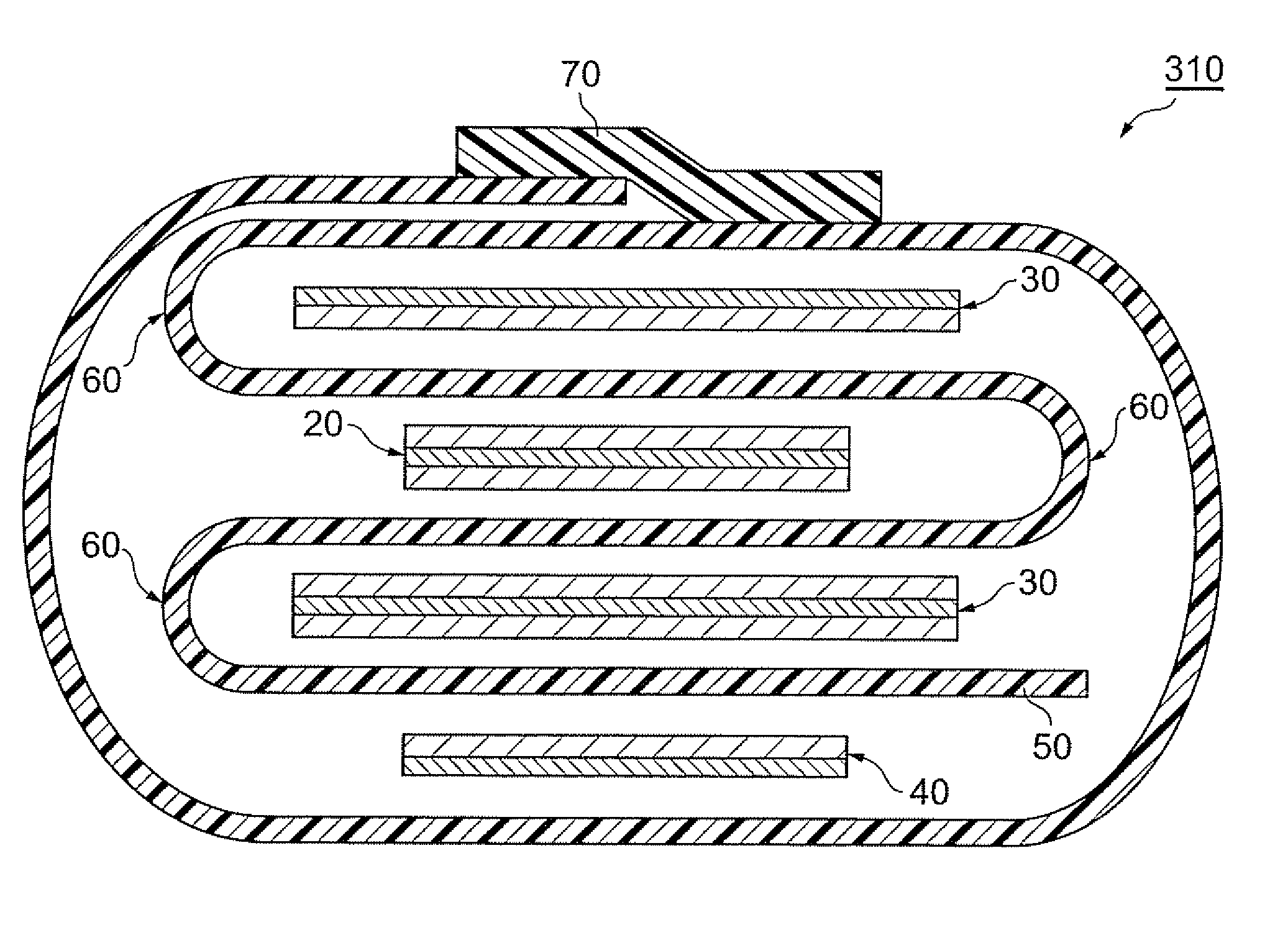
[0145]A laminate having a positional relationship for the electrodes and separator like that shown in FIG. 5 was then fabricated using the electrodes and separator fabricated as described above. In this laminate, the separator was folded in the same direction at two consecutive folds in which perforations were formed from one end thereof so as to form a structure in which one end of the separator surrounded the first anode, and folded at the subsequent folds in the manner of zigzag folding. Furthermore, the structure in which one end of the separator surrounds the first anode was formed using the same procedure as that of Examp...

example 3

[0147]A first anode and a first and second cathode were respectively prepared in the same manner as Example 1.

[0148]In addition, a porous film made of polyacrylonitrile resin (PAN) (47 mm long×128 mm wide, thickness: 24 μm) was prepared, and perforations were formed at three locations for each interval of 32 mm in the horizontal direction to obtain a separator.

[0149]A laminate having a positional relationship for the electrodes and separator like that shown in FIG. 7 was then fabricated using the electrodes and separator fabricated as described above. Namely, the separator was first arranged on the second cathode so that the second cathode was positioned between a first fold and a second fold by folding the separator at first through third folds from one end of the separator using the above folds at the three locations where the perforations were formed. Next, the first anode was respectively arranged between the first fold and the second fold and between the second fold and the thi...


PUM

PropertyMeasurementUnit
thicknessaaaaaaaaaa
thicknessaaaaaaaaaa
thicknessaaaaaaaaaa

Abstract

An electrochemical device including a first anode, a first cathode, a single continuous separator provided between the first anode and the first cathode and folded so as to be arranged on the opposite side of the first anode to the first cathode and on the opposite side of the first cathode to the first anode, and an electrolyte in contact with the separator, the first anode and the first cathode, wherein the separator has a shape that surrounds the periphery of the first anode or the first cathode by being folded in the same direction at two folds consecutive from one end of the separator.

Description

BACKGROUND OF INVENTION[0001]1. Field of the Invention[0002]The present invention relates to an electrochemical device such as a secondary battery or electrochemical capacitor, and to a production method thereof.[0003]2. Related Background Art[0004]Known examples of separators provided between a pair of electrodes in a conventional rectangular (sheet-like) electrochemical capacitor or lithium ion secondary battery include laminated types consisting of individual layers of discontinuous separators and folded types in which a single continuous separator is folded in a zigzag pattern (see, for example, Japanese Patent Application Laid-open Nos. 2002-329530, H7-57716 and H7-142086 and Published Japanese Translation No. 2004-503055 of a PCT International Publication).[0005]However, electrochemical devices using a laminated separator have poor work efficiency during production as a result of requiring the laminating of individual separators. In addition, since separators are only present ...

Claims


Application Information

Patent Timeline
Patent Type & Authority Applications(United States)
IPC IPC(8): H01M2/16H01M4/82H01G11/34H01G11/22H01G11/52H01M2/18H01M10/04H01M10/0583
CPCH01M10/0431H01M10/052Y10T29/49108Y02E60/122H01M10/0583Y02E60/10Y02P70/50
Inventor NAOI, KATSUONISHIZAWA, KENJIOHASHI, YOSHIHIKO
Owner TDK CORPARATION
Why Eureka
Try Eureka