
Ferrite paste, and method for manufacturing laminated ceramic component

a technology of laminated ceramics and ferrite paste, which is applied in the direction of nickel compounds, magnets, electrochemical generators, etc., can solve the problems of reducing affecting the shape retention of the component, and affecting the stability so as to achieve low flexibility, reduce the strength of the ferrite layer, and improve the effect of ferrite layer strength

Inactive Publication Date: 2008-11-20
TDK CORPARATION
View PDF13 Cites 12 Cited by
  • Summary
  • Abstract
  • Description
  • Claims
  • Application Information

AI Technical Summary

Benefits of technology

The present invention provides a ferrite paste and a method for manufacturing a laminated ceramic component that can reduce cracking in the ferrite layer. The ferrite paste contains a ferrite powder and an organic vehicle, which helps to make the ferrite layer more flexible and resistant to cracking. The binder used in the ferrite paste is made of a polyvinyl acetal resin and ethyl cellulose, which helps to maintain the strength of the ferrite layer and improve its shape retention. The thickness of the conductor pattern before burning is important in preventing cracking, and the polyvinyl acetal resin content should be set to at least 0.5 weight part and less than 1.0 weight part per 100 weight parts ferrite powder to keep cracking to an acceptable level.

Problems solved by technology

The thicker portion of the ferrite layer takes longer to dry than the thinner portion, so cracks tend to develop.
This cracking is also attributable to the hard and brittle properties of the ethyl cellulose resin contained as a binder in the ferrite paste.
Also, the thicker the conductor paste is, the greater is the difference in thickness of the ferrite layer, so the more likely cracking is to occur.
Also, with the conventional manufacturing method discussed above, debindering during heat treatment (debindering, burning, etc.) of the laminate lowers the strength of the ferrite layer, and shape retention tends to be low.
Therefore, as the conductor pattern shrinks, cracks are more likely to develop in the ferrite layer adhering to the conductor.

Method used


Image

  • Ferrite paste, and method for manufacturing laminated ceramic component
  • Ferrite paste, and method for manufacturing laminated ceramic component
  • Ferrite paste, and method for manufacturing laminated ceramic component

Examples


first embodiment

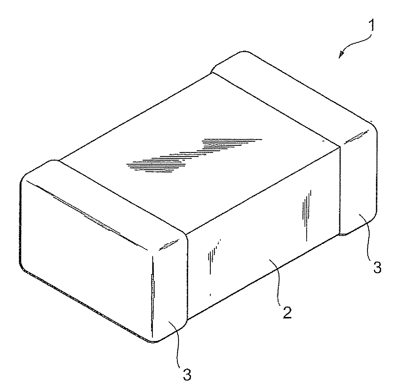
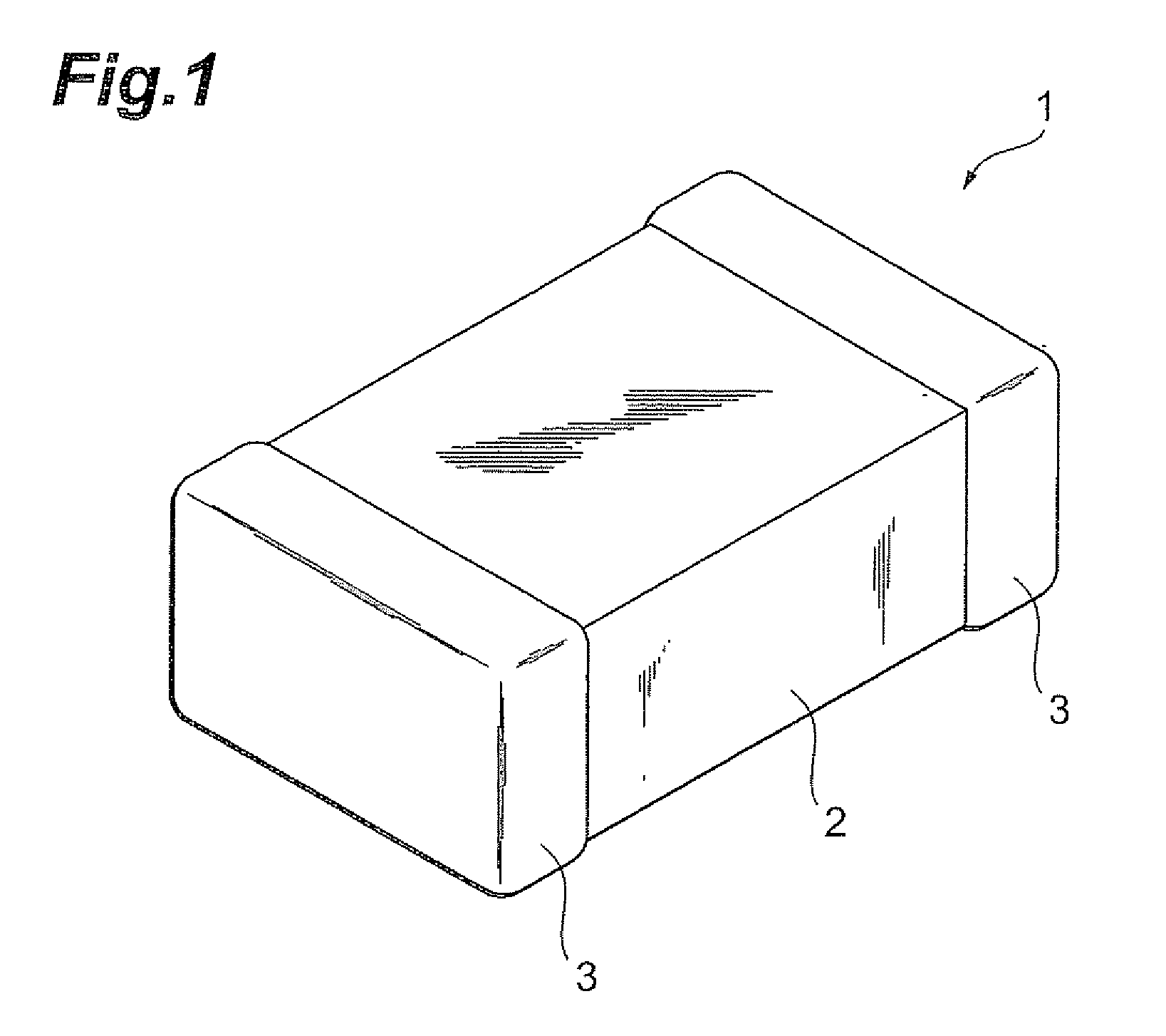
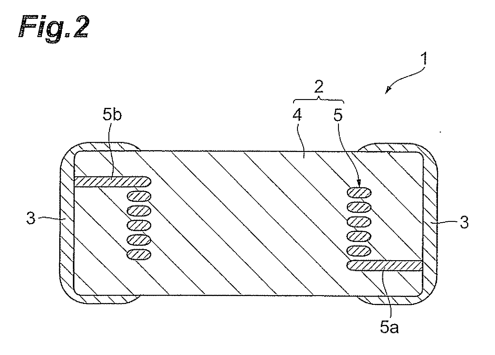
[0029]FIG. 1 is an perspective view of the structure of a laminated inductor produced using the method for manufacturing a laminated ceramic component pertaining to the first embodiment of the present invention. FIG. 2 is a cross sectional view along a line connecting the terminal electrodes of the laminated inductor shown in FIG. 1, and FIG. 3 is a cross sectional view perpendicular to that in FIG. 2.

[0030]As shown in FIG. 1, a laminated inductor 1 comprises a rectangular parallelepiped element 2 and a pair of terminal electrodes 3 formed so as to cover the two ends in the lengthwise direction of the element 2. As shown in FIGS. 2 and 3, the element 2 comprises a magnetic body laminated part 4 composed of a magnetic material, and a coiled conductor 5 formed inside the magnetic body laminated part 4.

[0031]The coiled conductor 5 is composed of a conductive material, and has a substantially semicircular cross sectional shape. Also, as shown in FIG. 2, extraction parts 5a and 5b corres...

second embodiment

[0051]Next, the ferrite paste and the method for manufacturing a laminated ceramic component pertaining to a second preferred embodiment of the present invention will now be described. The laminated inductor pertaining to the second embodiment has the same constitution as the laminated inductor 1 pertaining to the first embodiment.

[0052]First a ferrite paste and a conductor paste are produced. The ferrite paste is produced by combining and kneading a ferrite powder (magnetic powder) and an organic vehicle. The organic vehicle contains an organic solvent and a binder composed of a polyvinyl acetal resin and ethyl cellulose.

[0053]The binder content in the ferrite paste is at least 3.0 weight parts and no more than 5.0 weight parts per 100 weight parts ferrite powder. The polyvinyl acetal resin content in the ferrite paste is at least 1.0 weight part and no more than 2.0 weight parts per 100 weight parts ferrite powder. The ethyl cellulose content in the ferrite paste is the remainder ...

working examples

[0069]The present invention will now be described in further detail through working examples, but is not limited to or by these examples.


PUM

PropertyMeasurementUnit
thicknessaaaaaaaaaa
thicknessaaaaaaaaaa
inductanceaaaaaaaaaa

Abstract

The ferrite paste according to the present invention contains a ferrite powder and an organic vehicle, and the organic vehicle contains an organic solvent and a binder made of a polyvinyl acetal resin and ethyl cellulose. The binder content in the ferrite paste is at least 3.0 weight parts and no more than 5.0 weight parts per 100 weight parts of the ferrite powder, and the polyvinyl acetal resin content is at least 0.5 weight part and no more than 2.0 weight parts per 100 of the weight parts ferrite powder. The ethyl cellulose content is the remainder of subtracting the polyvinyl acetal resin content from the binder content.

Description

BACKGROUND OF THE INVENTION[0001]1. Field of the Invention[0002]The present invention relates to a ferrite paste and to a method for manufacturing a laminated ceramic component.[0003]2. Related Background Art[0004]In general, laminated ceramic components such as chip inductors, chip beads, chip transformers and LC composite chip components are manufactured by laminating a ferrite layer formed from a ferrite paste and a conductor pattern formed from a conductor paste, then burning this laminate and forming an external electrode thereon.[0005]An example of a laminated ceramic component is the laminated inductance element discussed in Japanese Patent No. 3035479. With this laminated inductance element, a conductor paste and a ferrite paste containing an ethyl cellulose resin as a binder are alternately laminated by printing, and this product is cut to the required size to form a laminate having a coiled conductor in its interior. This laminate is burned and an external electrode is for...

Claims


Application Information

Patent Timeline
Patent Type & Authority Applications(United States)
IPC IPC(8): C08K3/22B32B37/00
CPCC01G49/0018C01G53/006C01P2004/62C01P2006/40C01P2006/42H01F1/0027H01F1/113H01F1/37H01F41/16
Inventor ODA, KUNIOSUTOH, NAOKITAKAHASHI, YUKIOKAWASAKI, KUNIHIKOMOMOI, HIROSHI
Owner TDK CORPARATION
Learn More