Hybrid antenna including spiral antenna and periodic array, and associated methods

a spiral antenna and periodic array technology, applied in the field of hybrid antennas, can solve the problems of little, if any, room inside the equipment cabinet for installing testing hardware and its associated antennas, and commercial telecommunication providers customarily refuse to allow the use of rf radiating test equipment in their facilities

Inactive Publication Date: 2008-11-20
HARRIS CORP
View PDF20 Cites 21 Cited by
  • Summary
  • Abstract
  • Description
  • Claims
  • Application Information

AI Technical Summary

Benefits of technology

[0011]In view of the foregoing background, it is therefore an object of the present invention to provide an el

Problems solved by technology

However, there is a government agency ‘verification’ requirement (MIL-STD-188-125) that mandates the ability to test the shielding effectiveness of the protective structure subsequent to deployment of the equipment at a host facility, and such testing can be difficult or impossible due to the lack of room inside a densely populated shielded structure.
This strict verification requirement creates a two-fold problem that is typically encountered when attempting to conduct on-site testing of the electromagnetic radiation shielding-effectiveness of the protective enclosure.
Firstly, there is usually very little, if any, room inside the equipment cabinet to install testing hardware and its associated antenna, particularly once the cabinet has been integrated with other units at a host site, such as a comme

Method used


Image

  • Hybrid antenna including spiral antenna and periodic array, and associated methods
  • Hybrid antenna including spiral antenna and periodic array, and associated methods
  • Hybrid antenna including spiral antenna and periodic array, and associated methods

Examples


Embodiment Construction

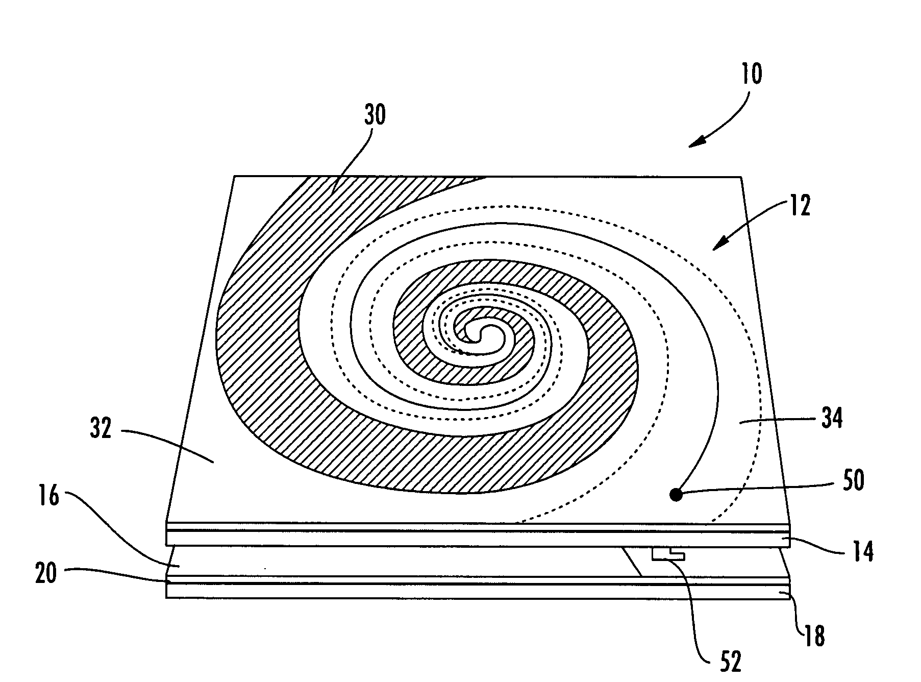
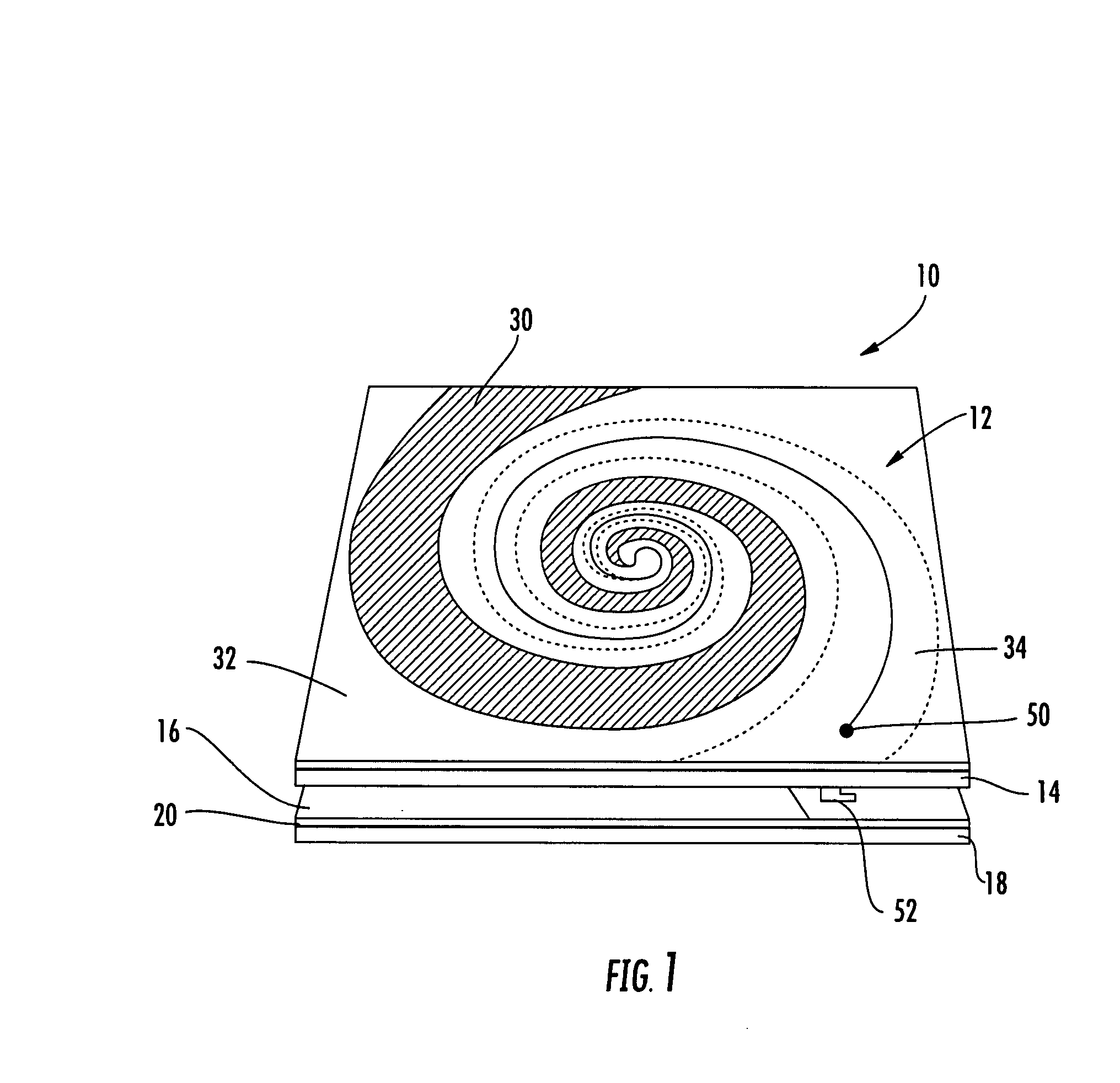
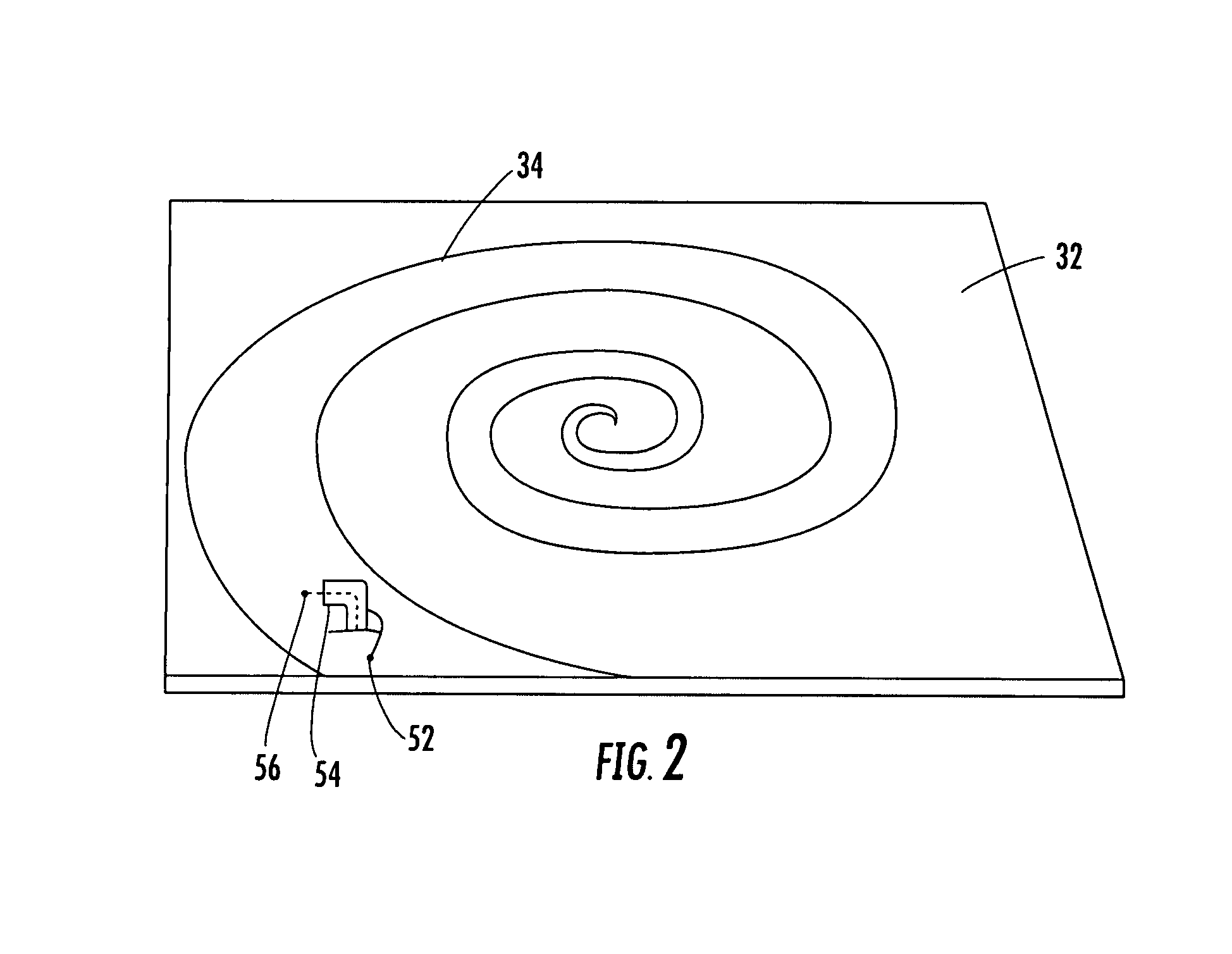
[0022]The present invention will now be described more fully hereinafter with reference to the accompanying drawings, in which preferred embodiments of the invention are shown. This invention may, however, be embodied in many different forms and should not be construed as limited to the embodiments set forth herein. Rather, these embodiments are provided so that this disclosure will be thorough and complete, and will fully convey the scope of the invention to those skilled in the art. Like numbers refer to like elements throughout. In the figures, the dimensions of layers and regions are exaggerated for clarity. It will also be understood that when a layer, sheet or region is referred to as being “on” another element, it can be directly on the other element or intervening layers, sheets or regions that may be present.

[0023]As discussed above, EPTSS may require efficient RF radiation in close proximity to conductive surfaces and equipment inside relatively small shielded equipment en...


PUM

PropertyMeasurementUnit
Dielectric polarization enthalpyaaaaaaaaaa
Electrical conductoraaaaaaaaaa

Abstract

The hybrid antenna includes a spiral antenna, e.g. a log spiral antenna, and a patch array layer adjacent to the spiral antenna and including a passive periodic patch array of conductive patch elements. A conductive ground plane may be adjacent to the patch array layer, and a dielectric layer may be between the conductive ground plane and the patch array. The spiral antenna may include an upper antenna arm, a lower antenna arm and a dielectric sheet therebetween. Each of the upper and lower antenna arms may be a printed planar conductive trace that is wider at a distal end thereof with respect to a center of the log spiral antenna. The patch or periodic array layer operates in conjunction with the ground plane to couple energy into the spiral antenna and thereby improve low frequency antenna efficiency while maintaining electrically small dimensions.

Description

FIELD OF THE INVENTION[0001]The present invention relates to the field of communications, and, more particularly, to antennas and related methods for wireless communications.BACKGROUND OF THE INVENTION[0002]To protect the circuit components of electronic equipment from potentially damaging electromagnetic radiation, such as an externally-sourced electromagnetic pulse (EMP) or other interference signals such as radar, broadcast radio and TV, Cellular Phone, etc., it is customary practice to house the equipment within some form of shielded structure such as a cabinet, or enclosure, for example. An adjunct to this shielding structure is the need to verify its shielding effectiveness, once the equipment has been deployed at a host facility. Up to the present, it has been conventional practice to conduct only ‘acceptance’ testing of the shielding for densely populated enclosures within a laboratory environment at the factory, and then assume that once it has passed the acceptance test, t...

Claims


Application Information

Patent Timeline
IPC IPC(8): H01Q1/36H01Q1/38H01Q9/04
CPCH01Q9/27Y10T29/49016H01Q15/006H01Q11/10
Inventor DELGADO, HERIBERTO J.HERNANDEZ, ARECIO A.HOYT, DAVID G.
Owner HARRIS CORP
Why Eureka
Try Eureka