Pyrolysis Systems, Methods, and Resultants Derived Therefrom

a technology of pyrolysis systems and resultants, applied in the field of pyrolysis systems and methods, can solve the problems of limiting the range of feedstocks that prior art pyrolysis systems could process, affecting the performance of communication systems, and long time-consuming, and achieves the effect of easy conformation and without undesired degradation of communication system performan

Active Publication Date: 2008-11-20
TUCKER RICHARD D
View PDF21 Cites 73 Cited by
  • Summary
  • Abstract
  • Description
  • Claims
  • Application Information

AI Technical Summary

Benefits of technology

[0014]A further aspect of the invention is a vapor barrier seal suitable for high-temperature applications that includes at least two vapor barrier collars and at least one detecting chamber that includes a sensor for detecting at least one of gases and gas pressures. The two vapor barrier collars encircle a shaft, such as an auger shaft, and the detecting chamber is disposed in between the two vapor barrier collars. In one embodiment of the invention, each vapor barrier collar is a stainless steel collar that encircles a shaft, with an annular groove formed along the inner circumference of the collar. Vapor pressure is delivered to the annular groove through holes in the collar. In an embodiment, the detecting chamber sensor determines if undesirable gases have passed through one of the vapor barrier collars, and if undesirable gases are detected, then additional vapor pressure is applied to one or more of the vapor barrier collars, thereby encircling the shaft with vapor. Another aspect of the invention is a method for preventing gases from escaping around a shaft while allowing the shaft to rotate freely, including the steps of mounting a shaft so that a portion of the shaft rotates within a detecting chamber and positioning vapor barrier collars around the shaft at opposite ends of the chamber. The method also includes detecting undesirable gases in the chamber, and raising the pressure in the vapor barrier collar to prevent undesirable gases from traveling through the vapor barrier collar.
[0016]It is yet a further aspect of the invention to utilize layers of communications control and data gathering for the control of at least one of individual pieces of equipment or machines, groups of machines within a plant, an entire plant operation, and a group of plants within a region. In an embodiment, the control system provides uniform and standard instrumentation and data for the plant operation on a regional or global basis. One objective is to provide the energy and product data available from these plants in a historical block of profile data such that the gas and / or electrical energy data may be easily conformed to trading floor data models. In an embodiment, standard communication protocols are used to provide seamless integration of energy generation and energy metering to advanced metering infrastructure. These can be managed via the utilization of standard or manufacturer defined tables, user defined tables, extended user defined tables, standard procedures and manufacturer procedures, pending table and pending procedure, bi-directional message and uni-directional messages (blurts). Data elements can also be encoded for utilization in global inter-system exchange, importation and exportation of control, data and parameters. In an embodiment, encoding is accomplished using file structures that define a communication context that is capable of connecting individual sensors, machines, plants, municipalities, geographical regions, regions of plants, and / or trading floors and other entities which utilize energy block data and time-critical sensory data. In an embodiment, an integrated modular pyrolysis system includes a MMS (Modular Management System) and MDMS (Meter Data Management System) and databases to provide site independent, network independent end-to-end transparent real-time communication and control system. The system can make use of transparent bridging enhancement technology that allows the control system to interoperate securely, privately and globally without undesired degradation of communication system performance. Transparent speed enhancement signaling connections may also be used between sensor, control and management devices.

Problems solved by technology

However, obtaining consistency in the pyrolysis products has long been a problem.
Prior systems have attempted to pass a gasification agent through a fluidized bed of solid; however, this requires a highly granular and reactive fuel for gasification, and as such is limited in its application.
Likewise, high and low temperature pyrolysis processes are each better suited to pyrolizing different feedstocks, limiting the range of feedstocks that prior art pyrolysis systems could process.
Furthermore, though both high-temperature and low-temperature pyrolysis processes produce combustible, high-BTU materials, these resultant combustibles are often lower grade and they often contain harmful impurities, such as heavy metals, which can contaminate the environment when these materials are combusted.

Method used


Image

  • Pyrolysis Systems, Methods, and Resultants Derived Therefrom
  • Pyrolysis Systems, Methods, and Resultants Derived Therefrom
  • Pyrolysis Systems, Methods, and Resultants Derived Therefrom

Examples


Embodiment Construction

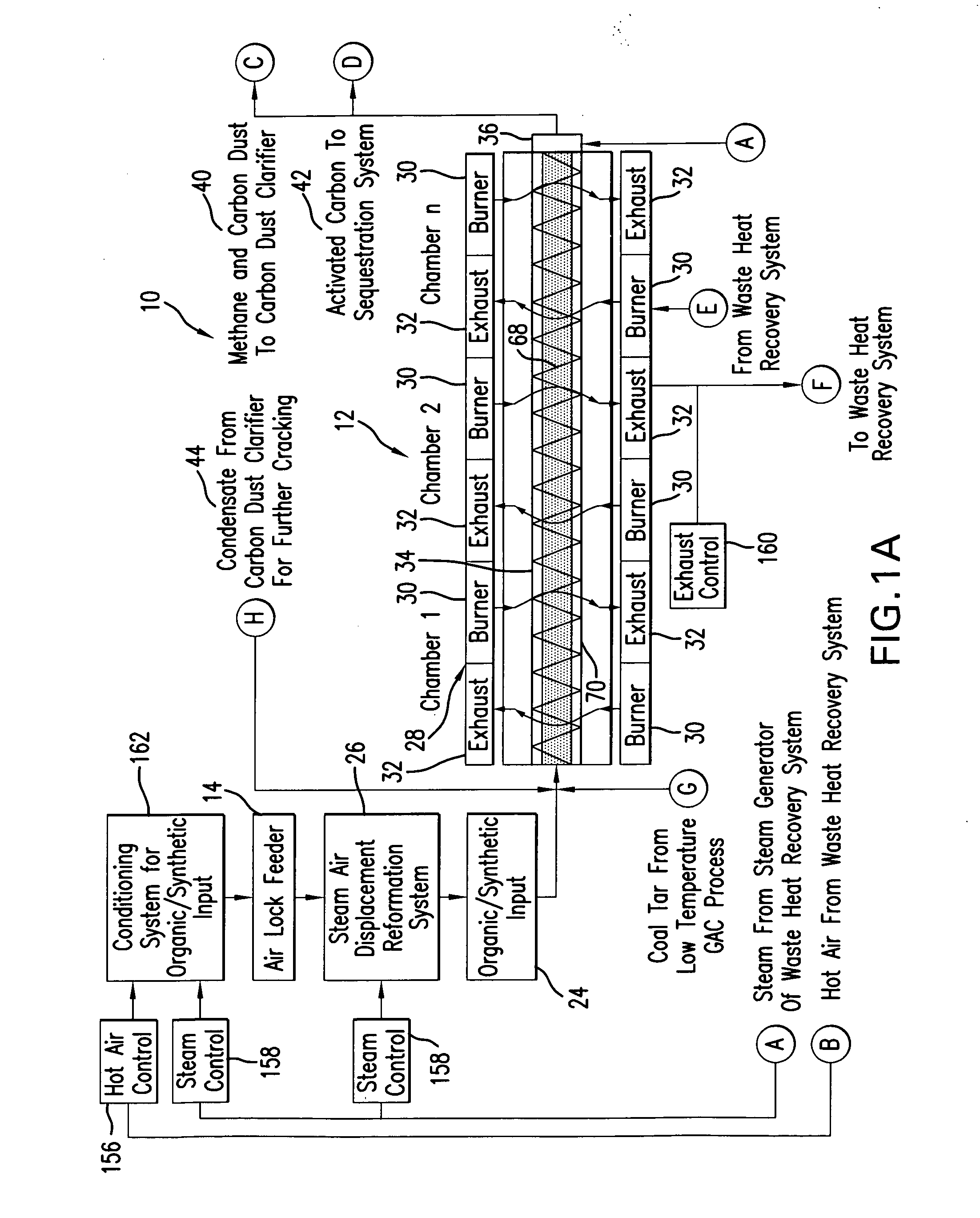
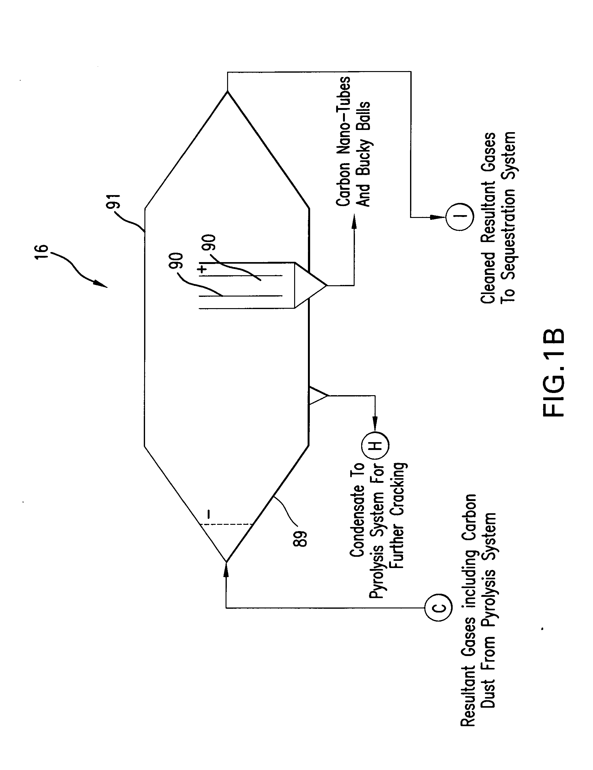
[0032]FIGS. 1A-1F are schematic diagrams showing components of a combined cycle carbonaceous feedstock conversion system 10 according to an embodiment of the present invention. The system 10 includes a high-temperature pyrolysis unit 12 that receives carbonaceous feedstock via an airlock feeder 14 and produces a gas product containing methane and a solids product containing activated carbon or non-activated carbon, depending upon the type of feedstock. The system 10 further includes a dust clarifier 16 for collecting carbon nanostructures from the gas and a series of filtering units 18 for removing noxious components from the gas using activated carbon from the pyrolysis unit. Also shown in FIGS. 1A-1F are an optional low-temperature batch distillation system 20 and a low-temperature granulated activated carbon (GAC) system 22 that are operated using waste heat from the high-temperature pyrolysis unit 12.

[0033]In use, organic or synthetic feedstock 24 is introduced to the system thr...


PUM

PropertyMeasurementUnit
temperaturesaaaaaaaaaa

Abstract

A system and process for gasification of a carbonaceous feedstock uses pyrolysis to produce a gas product, which may include methane, ethane, and other desirable hydrocarbon gases, and a solids product, which includes activated carbon or carbon. The gas product may then be filtered using at least a portion of the activated carbon from the solids product as a filtering medium. In an embodiment, at least some of the noxious chemicals are sequestered or removed from the gas product in one or more filtering steps using the activated carbon as a filtering medium. In a further embodiment, the filtering steps are performed in stages using activated carbon at different temperatures. A high-temperature pyrolysis system that produces activated carbon may be combined with another high-temperature pyrolysis system that does not produce activated carbon to provide filtering of noxious compounds using activated carbon from the first high-temperature pyrolysis system. A high-temperature pyrolysis system may be combined with one or more low-temperature feedstock conversion processes such that waste heat from the high-temperature pyrolysis system is used to operate the low-temperature process. A novel non-wetting carbon having pores fused with silica can be produced from using the system and process.

Description

CROSS REFERENCE TO RELATED APPLICATIONS[0001]This application claims priority from U.S. Provisional Patent Application No. 60 / 906,691, filed Mar. 14, 2007, U.S. Provisional Patent Application No. 60 / 997,791, filed Oct. 3, 2007, and U.S. Provisional Patent Application No. 61 / 007,965, filed Dec. 17, 2007, the contents of which are incorporated herein by reference in their entirety.BACKGROUND OF THE INVENTION[0002]I. Field of the Invention[0003]The present invention relates to a system and method for producing methane gas and carbon products from carbonaceous feedstock.[0004]II. Discussion of the Background Art[0005]Techniques for partial pyrolysis of feedstocks as well as complete pyrolysis and gasification are known. Furthermore, high-temperature and low-temperature pyrolysis processes are known, and it is known in the art that these different processes work best with different feedstocks and give different resultants. However, obtaining consistency in the pyrolysis products has long...

Claims


Application Information

Patent Timeline
Patent Type & Authority Applications(United States)
IPC IPC(8): C10B57/00C01B31/00B32B3/20C10B1/00C10B57/18
CPCC10B47/30C10B47/44C10B53/00C10B53/02C10B53/04C10G2300/807C10G1/02C10G1/10C10G2300/1003C10G2300/1011Y02E50/14C10G1/002Y02E50/10Y02P20/129Y02P30/20Y10T428/249987
Inventor TUCKER, RICHARD D.
Owner TUCKER RICHARD D
Why Eureka
Try Eureka