Aerogel Based Composites

a composite material and aerogel technology, applied in the field of syntactic foams and composites, can solve the problems of high cost, inability to meet the requirements of foam compression strength, etc., and achieve the effects of reducing density, increasing porosity, and reducing thermal conductivity of aerogels

Active Publication Date: 2008-11-20
CABOT CORP
View PDF19 Cites 91 Cited by
  • Summary
  • Abstract
  • Description
  • Claims
  • Application Information

AI Technical Summary

Benefits of technology

[0137]The aerogel particles used in the present invention can have hydrophobic surface groups. In order to avoid any subsequent collapse of the aerogels by the condensation of moisture within the pores, it is preferred that hydrophobic groups be covalently bonded on at least the inside surface of the aerogel. Preferred groups for permanent hydrophobization are mono-, di-, or tri-substituted silyl groups of the formulas:
[0138]The use of trimethyl- and dimethylsilyl groups for permanent hydrophobization of the aerogel can be particularly advantageous. These groups can be introduced as described in WO 94 / 25149 (incorporated in its entirety by reference herein) or by gas-phase reaction between the aerogel and, for example, an activated trialkylsilane derivative, such as a chlorotrialkylsilane or a hexaalkyldisilazane (cf. R. Iler, The Chemistry of Silica, Wiley & Sons, 1979).
[0139]Furthermore and within certain limits, the thermal conductivity of the aerogels can decrease as porosity increases and density decreases. For this reason, aerogels with porosities of greater than about 60% and densities of less than about 0.8 g / cc are preferred. More preferably, the aerogels of the present invention have densities of from about 0.01 to about 0.15 g / cc. The thermal conductivity of the aerogel particles can be less than 100 mW / m° K or less than about 40 mW / m° K, preferably, less than about 25 mW / m° K, and, more preferably, the thermal conductivity of the aerogel particles is from about 12 to about 18 mW / m° K, or lower. For purposes of the present invention, thermal conductivities are based on measurements at a mean temperature of 12.5° C. or at ambient temperatures, such as from 12.5° C. to 30° C.
[0140]The aerogels can have any particle size that allows them to be dispersed within the polymer matrix, such as from about 2 nm to 5 mm or from 40 nm to 1 mm, or from 10 micron to 1 mm. The aerogels can have various particle size distributions. The aerogels can be in the form of comminuted powders.
[0141]The aerogel can be present in any desirable amount to achieve the particular density and / or thermal conductivity of the overall composite. For instance, the aerogel can be present in an amount from about 1% to about 99%, and more preferably from about 20% to about 75% or from about 20% to about 60% based on the volume of the overall composite, wherein volume is based on gas present in the aerogel, without intrusion of polymer in the pores.
[0142]As stated earlier, the aerogel used in the composite of the present invention is coated or encapsulated to prevent intrusion (or substantial intrusion) of the polymer into the pores of the aerogel. The coating or coated aerogel or encapsulated aerogel for purposes of the present invention refers to a coating on the aerogel surface that prevents intrusion (or substantial intrusion) of the polymer (or of the other above described matrix materials such as ceramics and / or glass) from the matrix into the pores of the aerogel. This coating can be a shell, layer, or other similar type structure that is placed on the surface of the aerogel to prevent the intrusion or egress of the polymer (or of the other above described matrix materials such as ceramics and / or glass) from the matrix or continuous phase of a composite. The coating can be attached onto the surface of the aerogel by any means, such as chemical attachment adsorption, and the like. The layer forming the coating can be present as a physical layer with no adsorption or chemical attachment to the aerogel and simply remains intact due to its encapsulation around the aerogel. In more detail, the coating(s) can be an organic or inorganic coating. For instance, the coating can be a polymeric material and contained or be formed from one or more polymers. The coating can be a reactant or be polymerizable or initiate a polymerization. The coating can be a surfactant or wetting agent based coating. Other examples of coatings include, but are not limited to, polyvinyl acetate, epoxy, or nylon. Alternatively, the coating can be a wax or an inorganic material such as a ceramic or a glass. In at least one embodiment, the coating is applied as a wet coating in order to achieve uniform coating of the aerogels and then the wet coating or layer is dried in order to form a hard or cured coating that is not easily removable. In one or more embodiments, the coating layer on the aerogels is preferably a thin coating which serves to block the majority or all of the pores of the aerogel so as to prevent the subsequent intrusion of the material that forms the composite from entering into the pores of the aerogel. Generally, it is undesirable for the material of the composite to enter entirely the pores, such as the inner pore volume of the pores, of the aerogels since this would defeat the advantages achieved with the use of aerogels from the standpoint, for instance, of density reduction and / or reduction in thermal conductivity. It is preferred that the coating on the aerogel does not penetrate deeply into the pores of the aerogel for the same reason. Thus, the coatings used in the present invention can preferably bridge across the pores or block the pores or cover the pores of the aerogel, but preferably do not substantially penetrate into the pores of the aerogel. In one or more embodiments, preferably, the coating does not penetrate more than 10% of the overall diameter of the aerogel. As an example, if the diameter of the aerogel is 10 mm, preferably the coating does not penetrate more than 1 mm into the subsurface of the aerogel. The coating on the aerogel can be uniform, substantially uniform, or non-uniform. Again, preferably, whether uniform or non-uniform, the coating preferably blocks or bridges a majority or all of the pores of the aerogel exposed on the surface of the aerogel to prevent the material of the composite from entering these pores of the aerogel. Preferably, the coating on the aerogel has a layer thickness of from about 100 nm to about 3 mm, such as from about 0.5 micron to about 1 mm, or from about 0.5 micron to about 10 microns. The coating or layer on the aerogel can serve as an encapsulation of the aerogel. This encapsulation can be a full encapsulation or a partial encapsulation (e.g., 50%, 60%, 75% or more of the surface area). The following paragraphs describe various coatings and the formation of the coatings on the aerogel realizing that these examples are merely exemplary of the present invention.

Problems solved by technology

A lot of the blowing agents used in the past are no longer acceptable, and the ones developed in recent years are available at much higher costs.
Furthermore, the state of the art rigid foams prepared with blowing agents do not exhibit the high compression strength required when foams are used, i.e. in applications like deep sea pipeline insulation, up to 10,000 feet or higher.
These compositions are based on polymethylene poly(phenyl isocyanate) and result in low physical properties (i.e. tensile strength, elongation, etc.) which may be suitable for modeling stock applications, but not for the more demanding requirements in deep sea pipeline insulation.
Difficulties have been experienced, however, in producing syntactic foams that have a density which is comparable to conventional foams.
Thus, the density of syntactic foams have been limited by the void volume of the microspheres.
As such, the application of syntactic foams have been limited.

Method used


Image

  • Aerogel Based Composites
  • Aerogel Based Composites
  • Aerogel Based Composites

Examples


example 1

[0178]Nanogel® aerogel particles / PVA slurries were prepared by adding 10-micron sized Nanogel® particles (150 g) to 1.5 liters of a solution containing 150 g PVA and 20.5 g Barlox 12i (100% basis). After shaking and stirring, a slurry with a creamy consistency was formed, Laboratory drying of the slurry at 100° C. gave a layered structure, a top chunky layer, rich in PVA, a middle, powdery layer representing the bulk of the material and a bottom layer rich in PVA. Chunks of the top layer floated in isopropanol. The thermogravimetric study indicated that the sample contained 42 wt % Nanogel® particles (i.e., the PVA:Nanogel weight ratio was about 1.4:1). Mixing of the chunks into epoxy at 40 and 50 v % loadings (assuming the chunks had a density of 0.27 g / cc) gave composites that appeared to be pore-free. The epoxy containing 40 v % of the chunks floated in isopropanol. That containing 50 v % chunks was found to have a thermal conductivity of 93 mW / m° K, a value that compares very fa...

example 2

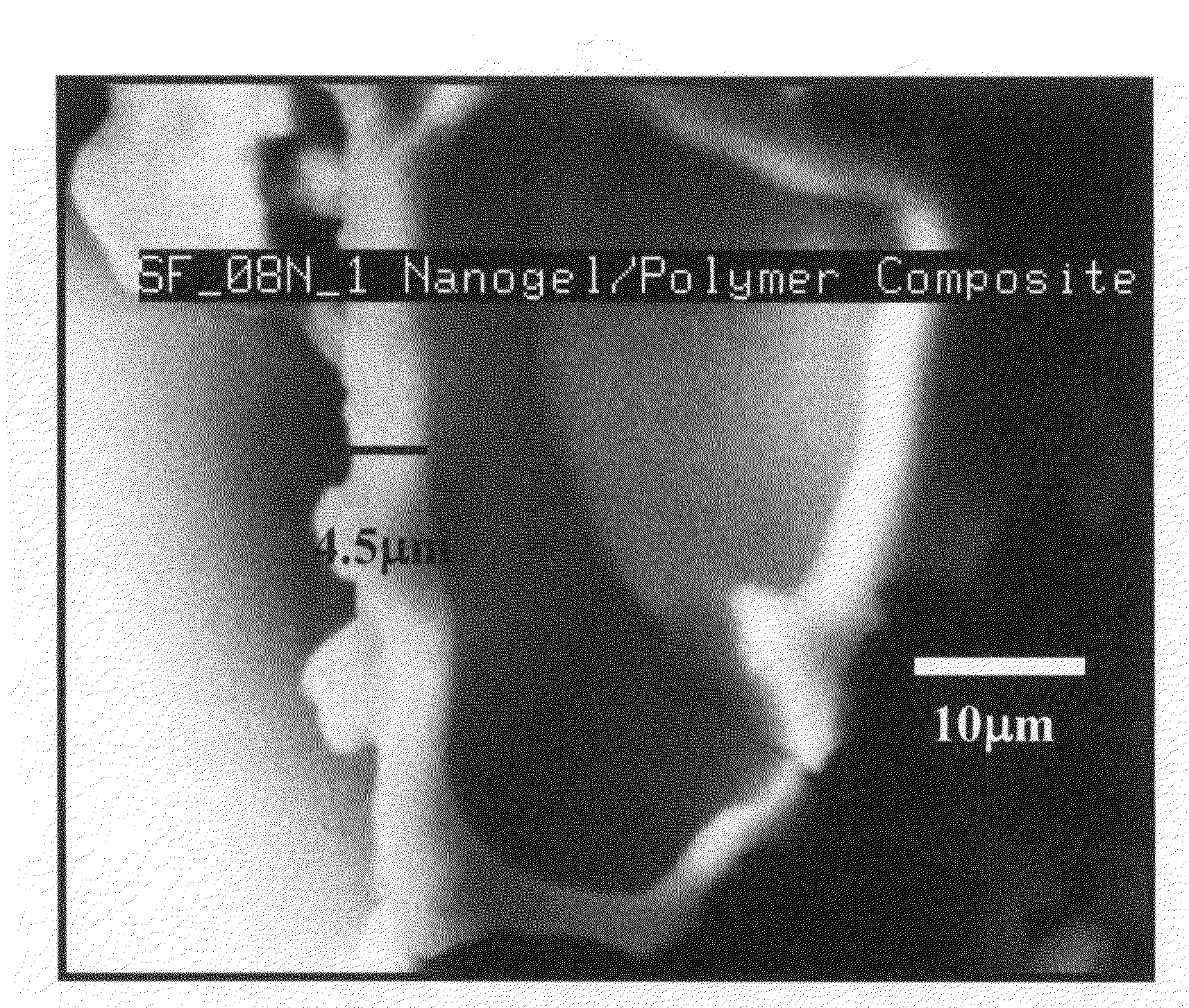
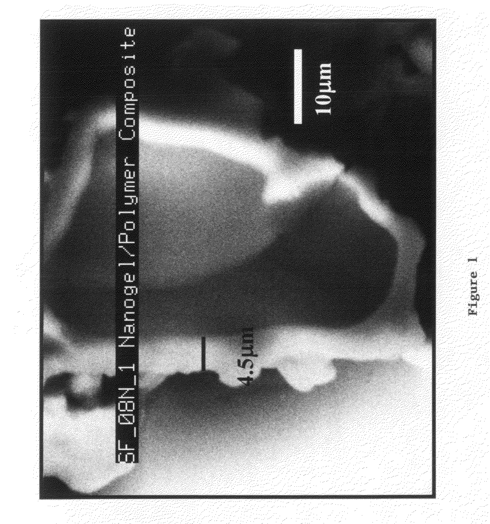
[0179]Nanogel Water Based Epoxy Composite: A water based epoxy emulsion / dispersion was used along with an aqueous curing agent. The epoxy emulsion / dispersion was stabilized using surfactants. The hydrophobicity of the Nanogel particle resisted the ingress of the solution. One pot mixture of water based epoxy (WBE), aqueous curing agent and Nanogel particles was gently stirred. The excess surfactant in the WBE aids in wetting the Nanogel particles and an intimate nanogel-epoxy composite was achieved. Nanogel grades TLD302, TLD101, 08N which were 3.0, 1.0, and 0.08 mm in size respectively were used. The composite was dried overnight followed by curing at 70° C. for 12 hrs and resulted in a light weight composite that exhibited favorable thermal performance.

[0180]Typical compositions used: (i) sample SF—08N: 16 g of EPI REZ 3515, 4 g of EPI KURE 8535, 3 g of Nanogel 08N (ii) sample SF—101: 16 g of EPI REZ 3515, 4 g of EPI KURE 8535, 6 g of Water, 4 g of Nanogel TLD 101. EPI REZ and EPI...

example 3

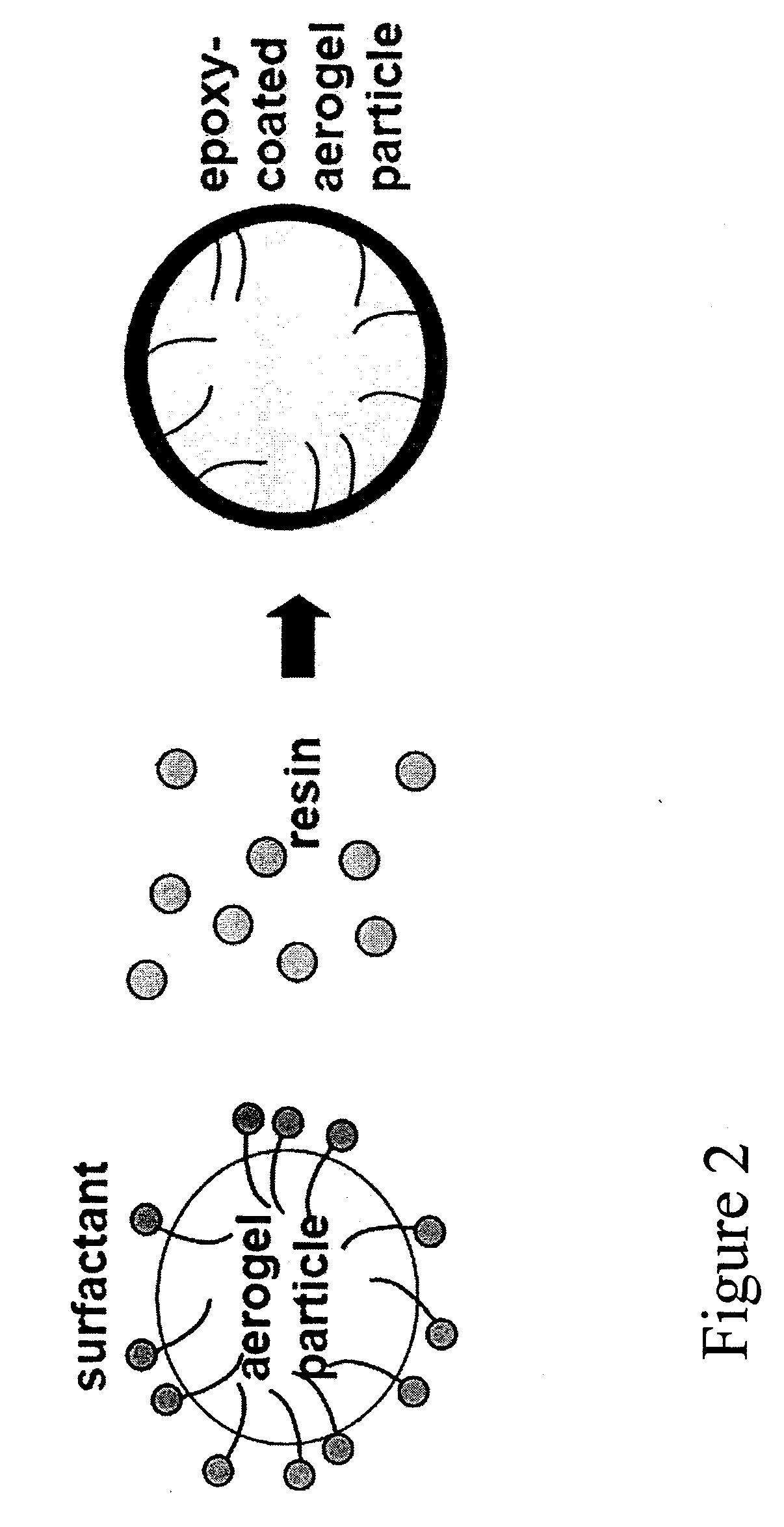
[0181]Water Based Epoxy Coated Nanogel Particle: Instead of mixing the curing agent in the aqueous mix as in Example 2 above, a surface active curing agent was used to decorate the surface of the Nanogel particles, resulting in a thin coating of epoxy forming on the Nanogel particle.


PUM

PropertyMeasurementUnit
thicknessaaaaaaaaaa
diameteraaaaaaaaaa
diameteraaaaaaaaaa

Abstract

Composites, such as syntactic foams, are described. The composite contains at least one polymer and at least one aerogel. The aerogel is coated with a coating substance to at least substantially prevent the intrusion of the polymer into the pores of the aerogel. Methods of making the composite are also described, as well as uses of the composite.

Description

[0001]This application is a continuation of PCT / US06 / 041114, filed Oct. 20, 2006, which in turn claims the benefit under 35 U.S.C. §119(e) of prior U.S. Provisional Patent Application No. 60 / 728,948, filed Oct. 21, 2005, and U.S. Provisional Patent Application No. 60 / 730,598, filed Oct. 27, 2005, which are all incorporated in their entirety by reference herein.BACKGROUND OF THE INVENTION[0002]The present invention relates to syntactic foams and composites, as well as methods for preparing the same and uses for the syntactic foams and composites. More particularly, the present invention relates to syntactic foams and composites which contain aerogels.[0003]Syntactic foam is generally considered prefabricated, manufactured “bubbles” or microsphere fillers in a resin milieu. Syntactic foams are composite materials whose resinous matrix is embedded with preformed particles such as glass or ceramic microspheres. Syntactic foams distinguish themselves from other foams by the fact that hol...

Claims


Application Information

Patent Timeline
Patent Type & Authority Applications(United States)
IPC IPC(8): C08J5/00C04B14/00
CPCC08J9/0066C08K7/26C08J2363/00C08J9/32C08K7/22C08K9/00C08L101/00
Inventor MENASHI, JAMEELBAUER, ULRICHPOTHMANN, ELMARPETERSON, ANDREW A.WILKINS, ANNA K.ANTON, MIHAIDOSHI, DHAVAL A.DALZELL, WILLIAM H.
Owner CABOT CORP
Why Eureka
Try Eureka