Solar collection and conversion system and methods and apparatus for control thereof

Inactive Publication Date: 2008-11-27
SOLAR TURBINE GROUP INT
View PDF27 Cites 67 Cited by
  • Summary
  • Abstract
  • Description
  • Claims
  • Application Information

AI Technical Summary

Benefits of technology

[0006]In one aspect, the present invention relates to a solar energy collection and conversion system including a solar energy collector, a vaporizer, an expander, a condenser, and a compressor, each in fluidic communication with the immediately preceding component, and further a conduit for fluid transportation, and a controller. The solar energy collector transfers solar energy to a first fluid, thereby elevating the temperature of said first fluid; the vaporizer transfers thermal energy from the first fluid to a second fluid, thereby elevating the temperature of the second fluid, the expander converts the thermal energy of the second fluid into mechanical energy, the condenser reduces the temperature of the second fluid; and the compressor pumps the second fluid at least partially through the vaporizer. The conduit is configured to transport the first or the second fluid, or both, between two or more of the following components: the solar energy collector, the vaporizer, the expander, the condenser, and the compressor. The controller controls one or more parameters associated with at least one of the collector, the vaporizer, the expander, the condenser, and the compressor. At least one of the vaporizer, the expander, the condenser, the compressor, the conduit, and the controller contains a component adapted for use in a non-solar power generation system application. In some embodiments, the first and/or the second fluid also includes a fluid adapted for use in a non-solar power generation system application. In various embodiments, the system further includes a heat exchanger for transferring thermal energy from the second fluid to a third fluid, thereby elevating the temperature of the third fluid, which may be a portable fluid or contain a fluid used in a thermal absorption-chiller cycle. In some embodiments, the second fluid has a first state at a location proximate the compressor and a second state at a location proximate the expander; and the system may further contain a recuperator which transfers thermal energy to a first state from a second state of the second fluid. The system can also contain, downstream of the expander, a second expander. In some embodiments, the system further includes a second collector, which can be a biogas energy collector, a waste heat recovery steam generator, and/or a geothermal energy collector.
[0007]In another aspect, the invention relates to a low-cost method for converting solar energy by collecting it, using it to heat a first fluid, transferring thermal energy from the first fluid to a second fluid, converting thermal energy of the second fluid into mechanical energy, and extracting thermal energy from the second fluid, and therein pumping the second fluid through a fluidic circuit, controlling a parameter associated with at least one of the collection and conversion steps, and utilizing a component adapted for use in a non-solar power generation system application. The fluidic circuit can be open or closed. Some embodiments further include converting mechanical energy into electrical energy; and this additional step can (but does not have to) utilize a component adapted for use in a non-solar power genera

Problems solved by technology

These conditions, which help ensure efficient operation of all the components of the thermodynamic engine, generally can not be met in small power plant installations desired by and beneficial to remote communities lacking a traditional energy grid.
First, employing a full-time staff member is rarely economically feasible, relative to the cost of the technology; therefore, an autonomous installation is desirable.
Third, rural and

Method used


Image

  • Solar collection and conversion system and methods and apparatus for control thereof
  • Solar collection and conversion system and methods and apparatus for control thereof
  • Solar collection and conversion system and methods and apparatus for control thereof

Examples


example

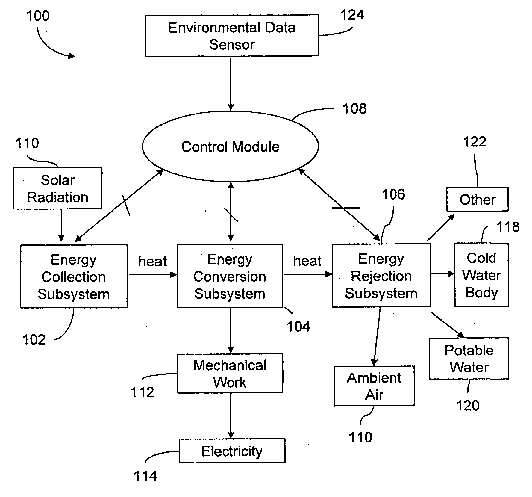
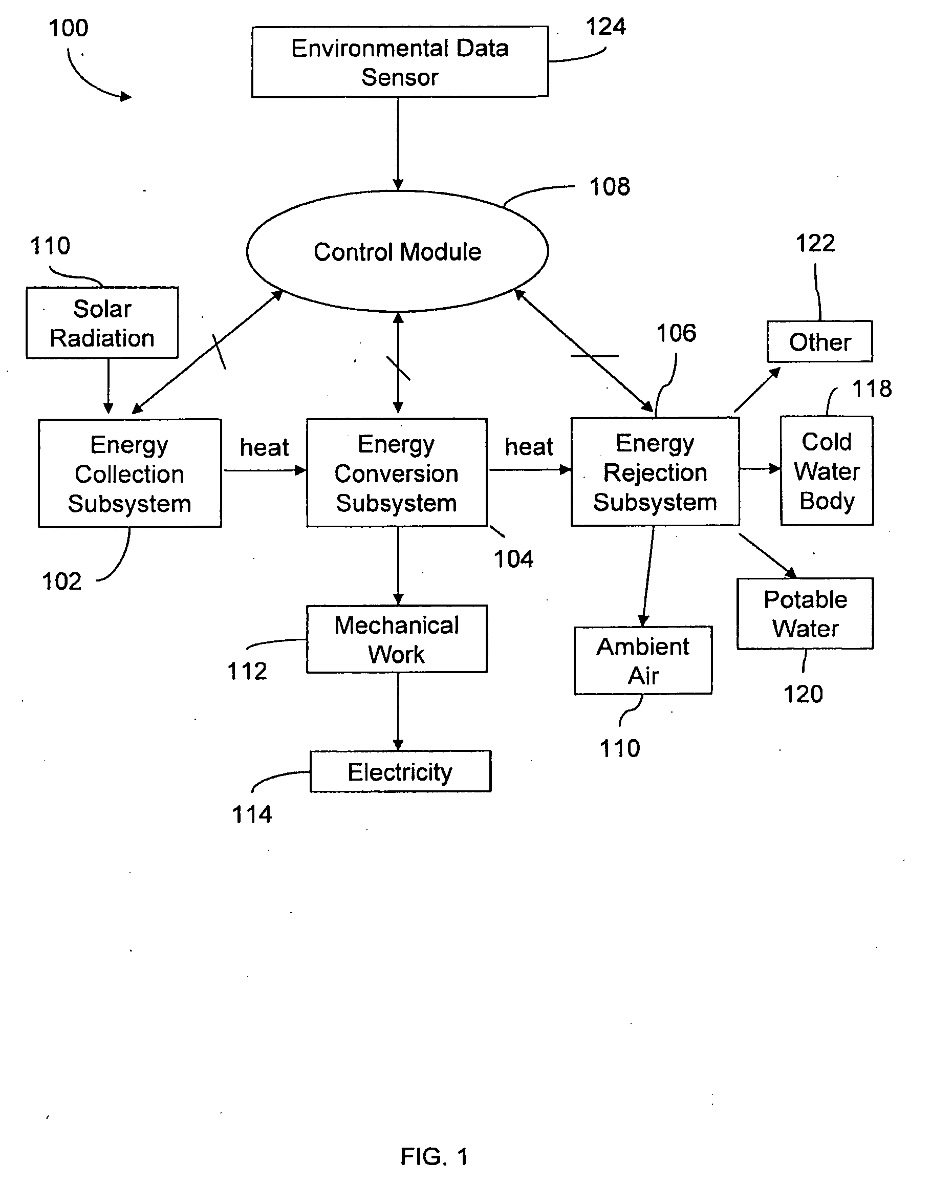
[0083]One particular embodiment of the invention, in the following also referred to as Microgenerator System 1 (the MS1), uses an organic Rankine cycle (ORC) in recuperative configuration and with three expansion stages to provide electricity and hot water. The system receives energy through solar collectors, and rejects waste heat to cooling water and ambient air. A control module interfacing with the ORC and solar collectors through sensors determines system operation parameters, and stores electrical energy generated in the ORC, which is in turn used to power components of the ORC and the solar collection and energy rejection systems.

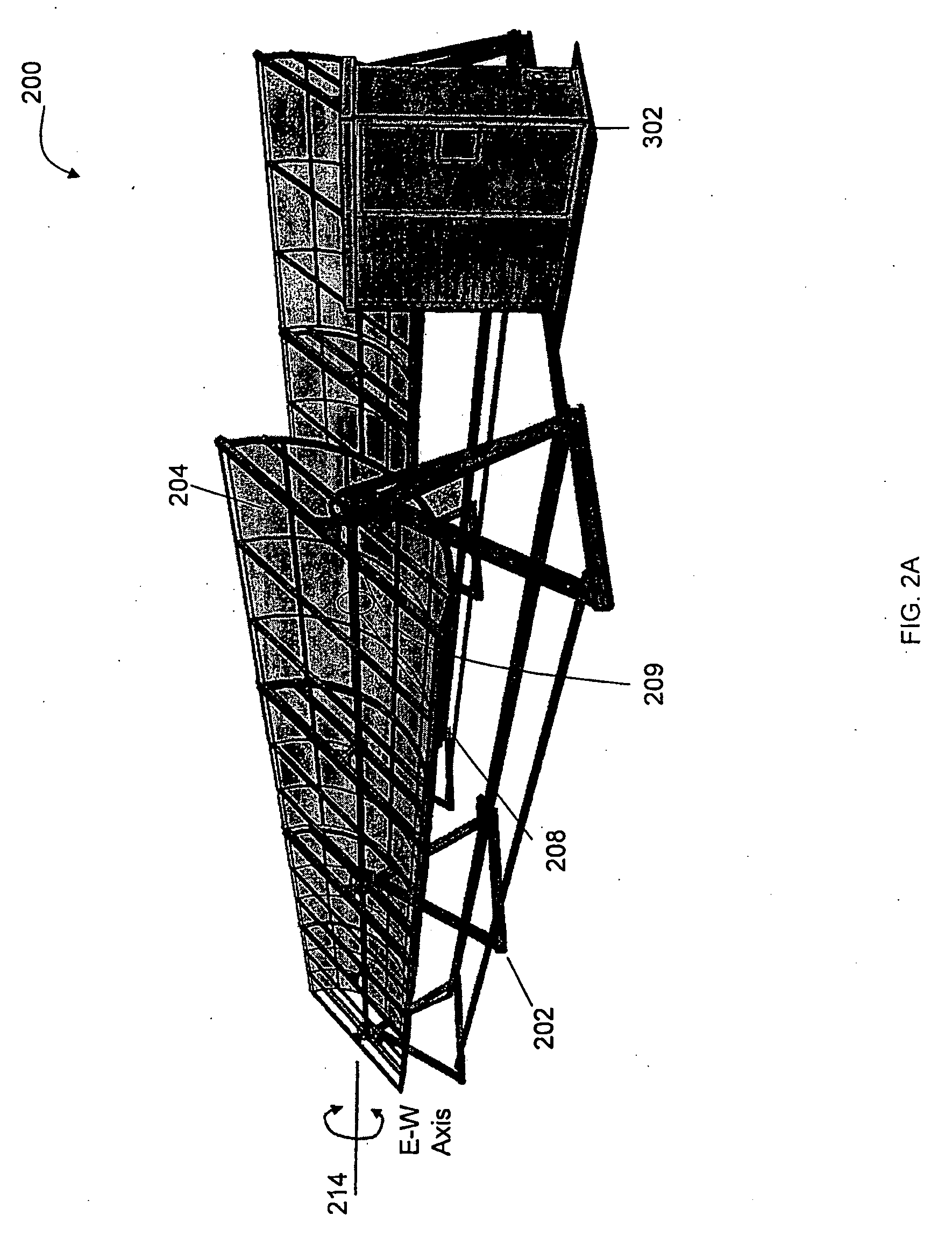
[0084]In operation, the system's parabolic trough reflectors collect solar energy and concentrate it into a thermal glycol fluid. In a heat exchanger, the hot glycol transfers some of its heat to, and thereby heats and ultimately vaporizes, the cool working fluid (a refrigerant, namely R245fa) of the ORC, which passes through the heat exchanger in th...


PUM


Abstract

Systems and methods for collecting solar energy and converting it to heat, mechanical work, or electricity on a small scale and utilizing one or more system components originally adapted for use in a non-solar-power-generation application are described. Solar energy is used to heat a fluid that is part of a solar energy collector. This fluid transfers heat to the working fluid of thermodynamic engine, which converts some of the heat into mechanical work or electricity. One or more system parameters are monitored and controlled to enable improved efficiency under variable environmental conditions.

Description

RELATED APPLICATIONS[0001]This application incorporates by reference in its entirety and claims priority to U.S. Provisional Patent Application Ser. No. 60 / 928,234, entitled “Low-Cost Solar Energy Collection and Conversion System,” filed on May 8, 2007.TECHNICAL FIELD[0002]The present invention relates generally to solar energy collectors and thermodynamic heat engines and, more specifically, to small-scale solar energy collection and conversion systems.BACKGROUND[0003]Organic Rankine cycles are typically used in megawatt-scale power plants, where power production and equipment are monitored at all times by human staff. At such plants, a specified turbine inlet pressure is necessary to maintain efficient operation. Constant heat input and output temperatures help maintain efficiency at the rated output. To compensate for periods of reduced or no solar insolation, one or more auxiliary heat source(s) may be utilized to maintain a constant heat input. Efficient heat rejection, and the...

Claims


Application Information

Patent Timeline
IPC IPC(8): F03G6/00F03B15/00G05D7/00
CPCF03G6/067F24J2/055F24J2/14F24J2/40F24J2/541F24J2/5427F24J2002/5458Y02E10/46F24S23/74F24S2030/133F24S30/458F24S30/425F24S10/45F24S50/00
Inventor OROSZ, MATTMUELLER, AMYWAYMAN, ELIZABETHJACOBUS, HEADLEYURBAN, BRYAN
Owner SOLAR TURBINE GROUP INT
Why Eureka
Try Eureka