Novel composite tool holders and boring tools

a tool holder and composite technology, applied in the direction of chucks, synthetic resin layered products, natural mineral layered products, etc., can solve the problems of low bending strength, low stiffness, and generation of bending phenomenon in the tool, and achieve better dampening effect of the tool, higher angle, and more rigidity

Inactive Publication Date: 2008-11-27
KAY DONALD ELWOOD
View PDF12 Cites 11 Cited by
  • Summary
  • Abstract
  • Description
  • Claims
  • Application Information

AI Technical Summary

Benefits of technology

[0037]The composites of this invention can be wrapped in various configurations, depending on the amount of dampening and stiffness required in the tool. For example, the composites can be wrapped on the tool in a configuration having an angle of from 0° to 90° from the linear long axis of the tool. The closer the wrap is to 0°, the better the dampening effects of the tool, while higher angles provide more stiffness.

Problems solved by technology

This configuration leads to low bending strength and low stiffness and thus, a bending phenomenon in the tool is generated.
Accordingly, upper thresholds of cutting speeds and feed rates are low, and it is impossible to consistently machine accurate deep holes.
It is difficult to machine cemented carbides.
Further, since frequency of a boring bar or a reaming bar is low due to high densities of tungsten carbide and tool steel, there is a limitation on improvement of the cutting speed of the bar.

Method used


Image

  • Novel composite tool holders and boring tools
  • Novel composite tool holders and boring tools
  • Novel composite tool holders and boring tools

Examples


Embodiment Construction

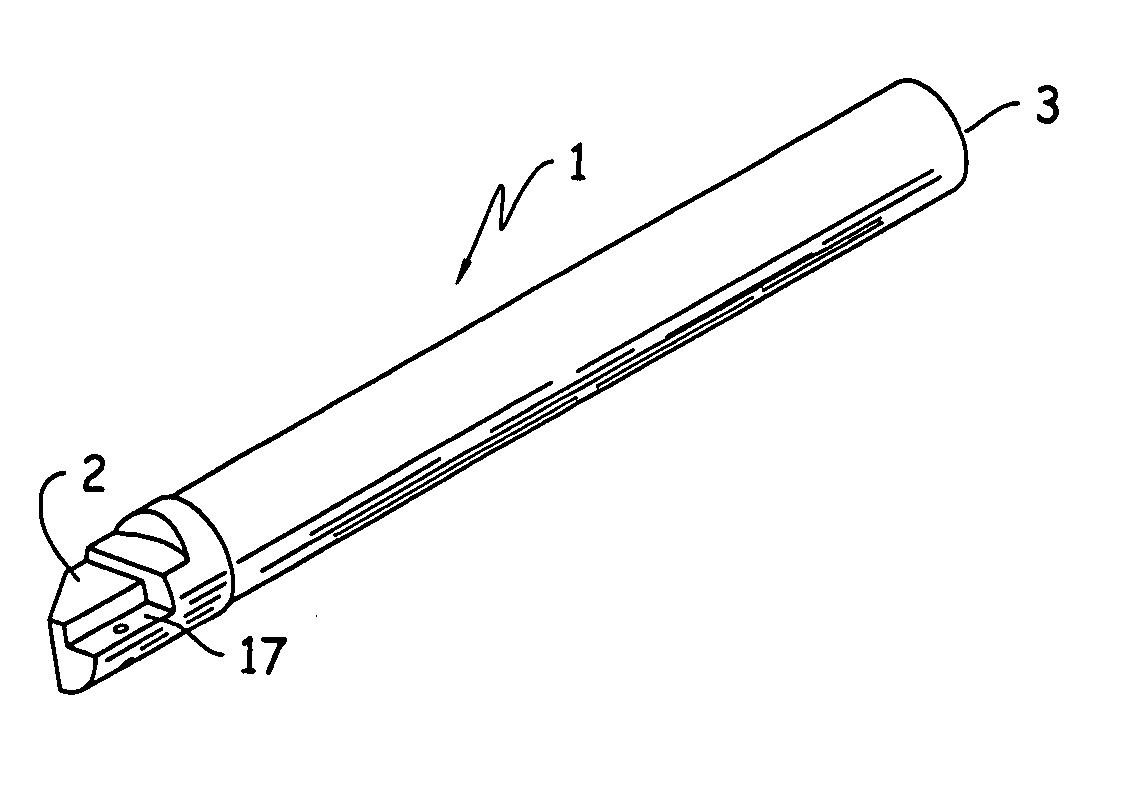
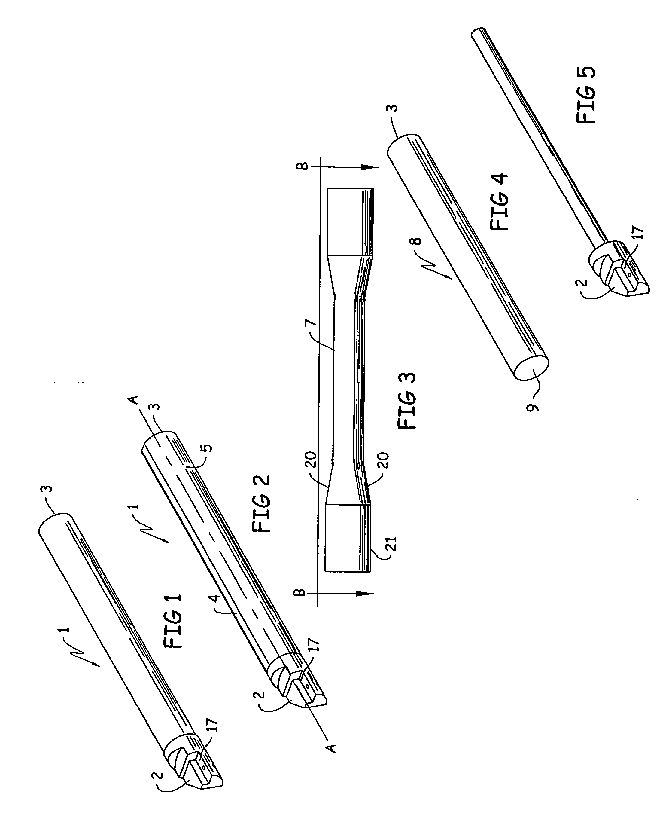
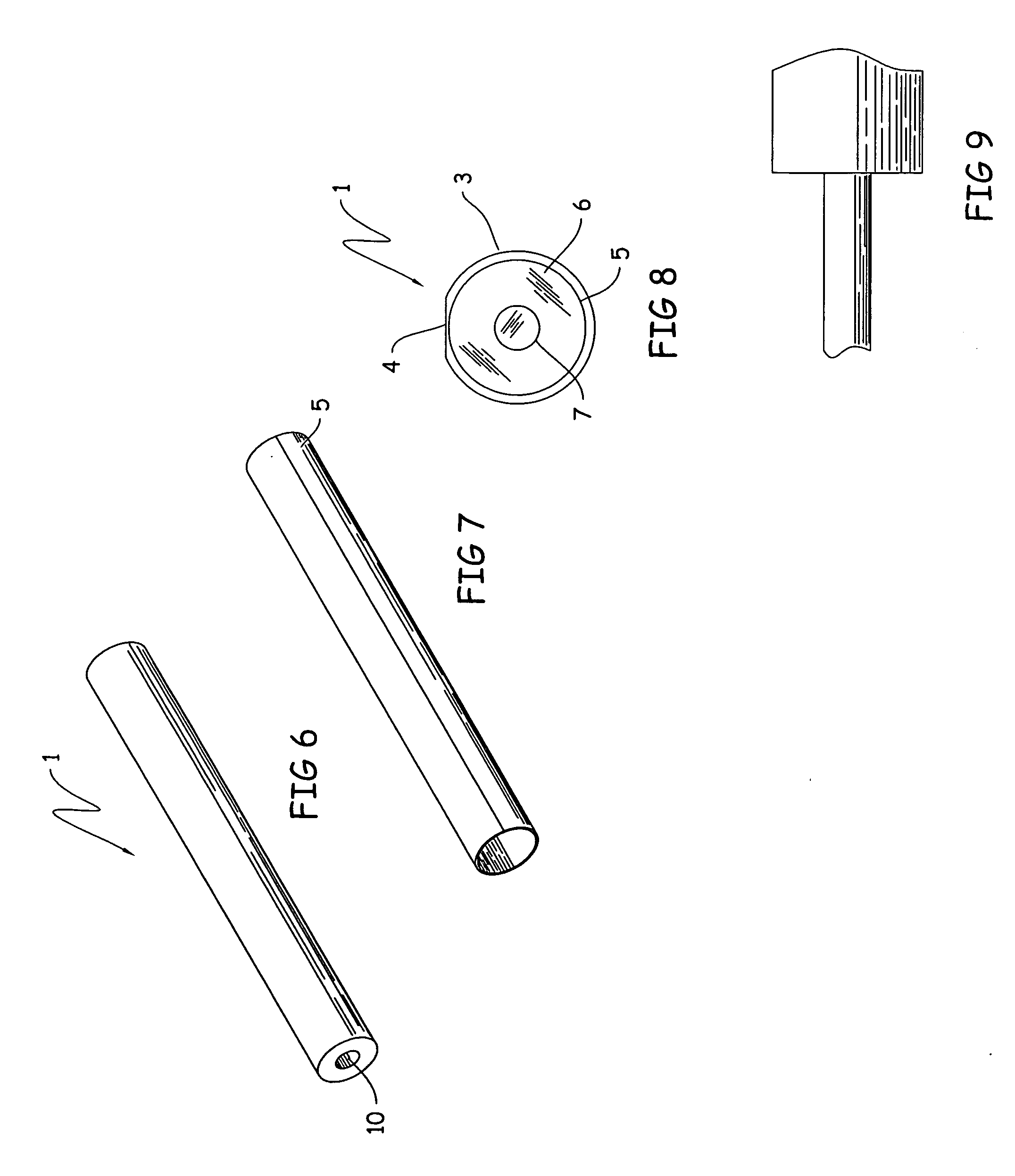
[0060]Turning now to FIG. 1 of this invention that is a view in perspective of a finished tool bar 1 of this invention, there is shown the boring head 2, the back end 3, and in FIG. 2, the flat surface 4 along the long axis A-A of the tool bar 1. With reference to FIG. 8, there is shown a full back end 3 view of the finished tool bar 1, showing an exterior steel covering 5, the composite material 6, the mandrel stem 7, and the flat surface 4 along the long axis.

[0061]Turning now to FIG. 3, there is shown one embodiment which is a mandrel stem 7 that shows the arcuate step down 20 from the front end 21 to the mandrel stem 7. It is believed by the patentees herein that this arcuate step down 20, as opposed to a sharp angled step down increases the strength of the boring bar by putting less stress on the mandrel stem 7 at this point in the configuration.

[0062]Turning now to another embodiment of this invention that is a method of manufacturing the boring tool 1, the method comprises pr...


PUM

PropertyMeasurementUnit
angleaaaaaaaaaa
lengthaaaaaaaaaa
Rockwell Hardnessaaaaaaaaaa

Abstract

Tool bars that are manufactured as a composite, that is, layered devices. The tool bars can have a solid core, covered with a wrapped composite material, and then optionally covered with a metal sleeve. The tool bars are provided with high strength, improved stiffness over prior art tool bars, high density, low coefficient of thermal expansion, high damping capacity, improved rigidity, improved damping, less chatter and vibration, improved work piece tolerance, improved surface finish, increased speed/fee rates, and low production cost.

Description

[0001]This application claims priority from U.S. provisional patent application Ser. No. 60 / 902,996, filed Feb. 22, 2007.[0002]The invention disclosed and claimed herein deals with tool bars that are manufactured as a composite, that is layered devices, that provide the tool bars with high strength, improved stiffness over prior art tool bars, high density, low coefficient of thermal expansion, high damping capacity, improved rigidity, improved damping, less chatter and vibration, improved work piece tolerance, improved surface finish, increased speed / fee rates, and low production cost.BACKGROUND OF THE INVENTION[0003]The tool bars of this invention have heretofore been manufactured from steel or other hardened metal and in at least one tool, composite segments, that is, portions of the tool were manufactured from composites.[0004]Tool bars for use in the mounting of cutting tools, such as conventional boring and reaming bars, are manufactured to be elongated in order to machine dee...

Claims


Application Information

Patent Timeline
Patent Type & Authority Applications(United States)
IPC IPC(8): B23B51/00B32B15/04B32B9/00B32B27/34
CPCB23B29/022B23B29/12Y10T408/94B23B2226/27B23B2226/275B23B2222/84Y10T428/31678Y10T428/31725
Inventor KAY, GREGORY J.THERIAULT, RICHARDSCHOENLEBER, LAWRENCE
Owner KAY DONALD ELWOOD
Why Eureka
Try Eureka