Catalyst temperature control system for a hybrid engine

a temperature control system and hybrid engine technology, applied in the direction of electric control, machines/engines, transportation and packaging, etc., can solve the problems of lnts having several limitations, significant reduction of catalytic efficiency, adversely affecting engine efficiency

Active Publication Date: 2008-12-04
CATERPILLAR INC
View PDF21 Cites 40 Cited by
  • Summary
  • Abstract
  • Description
  • Claims
  • Application Information

AI Technical Summary

Benefits of technology

[0008]One aspect of the present disclosure is directed toward a temperature control system, including a controller configured to receive a signal representative of a temperature associated with a selective catalytic reduction (SCR) catalyst configured to receive an exhaust gas stream produced by a hybrid engine. The controller is also configured to transmit a first signal to a generator operably coupled to a battery and the hybrid engine, and to transmit a second signal to a heater configured to heat the SCR catalyst, wherein the first and second signals are configured to regulate the temperature associated with the SCR catalyst.
[0009]Another aspect of the present disclosure is directed to a power system, including a hybrid engine configured to produce an exhaust gas stream. The power system also includes a generator operably coupled to the hybrid engine and configured to supply electrical power to a battery, a selective catalytic reduction (SCR) catalyst configured to receive the exhaust gas stream, and a heater configured to heat the SCR catalyst. Additionally, the power system includes a controller operably connected to the generator and the heater, wherein the controller is configured to receive a signal representative of a temperature associated with the SCR catalyst.

Problems solved by technology

However, exhaust gas temperatures can fluctuate dramatically during normal engine operation, and these fluctuations can significantly reduce catalytic efficiency.
Although the system of the '215 application may reduce emission levels, LNTs have several limitations.
Also, the system of the '215 application requires torque sensors or other devices to dampen engine oscillations caused by frequent LNT regeneration, and frequent switching between rich and lean operating conditions can adversely affects engine efficiency.

Method used


Image

  • Catalyst temperature control system for a hybrid engine
  • Catalyst temperature control system for a hybrid engine
  • Catalyst temperature control system for a hybrid engine

Examples


Embodiment Construction

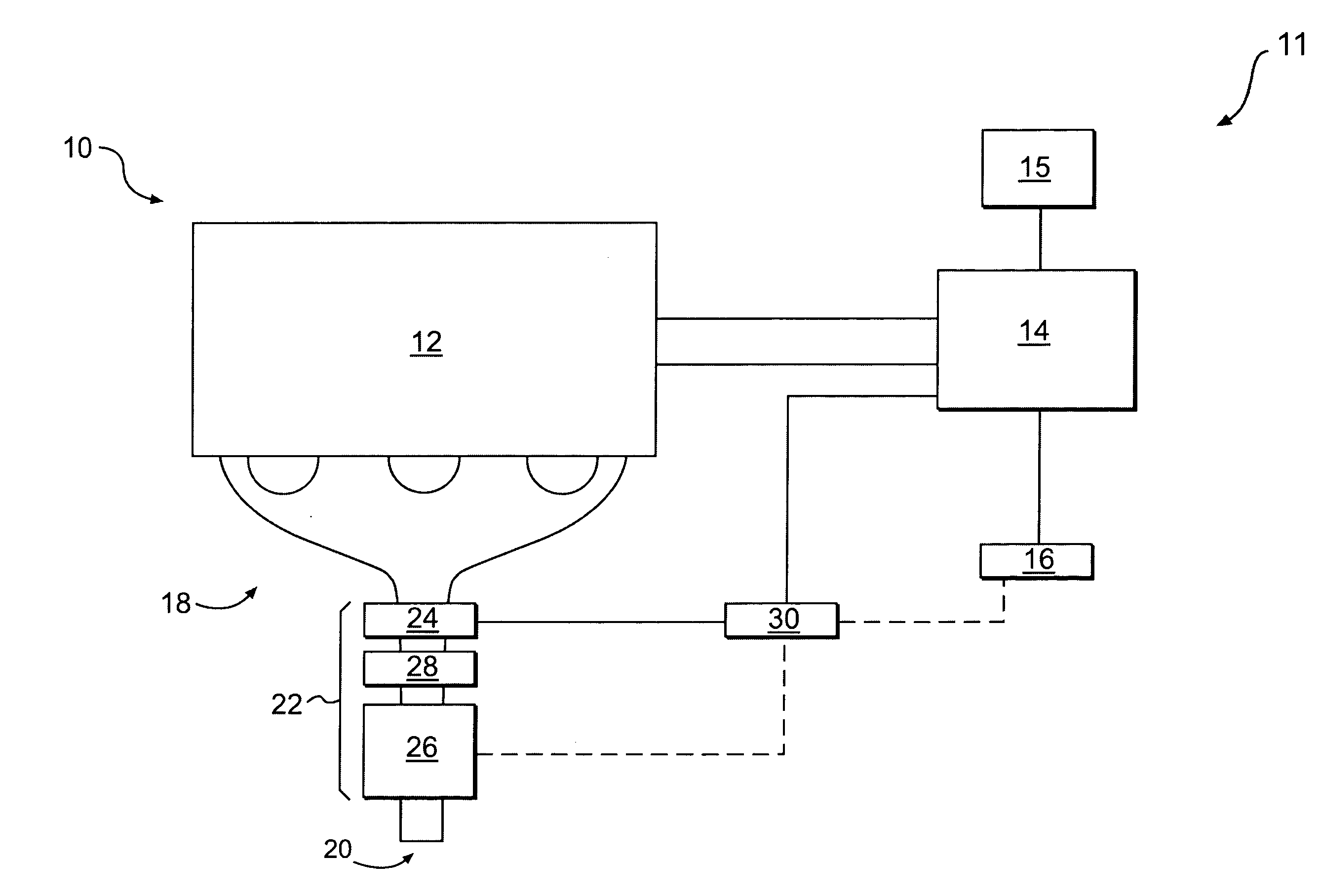
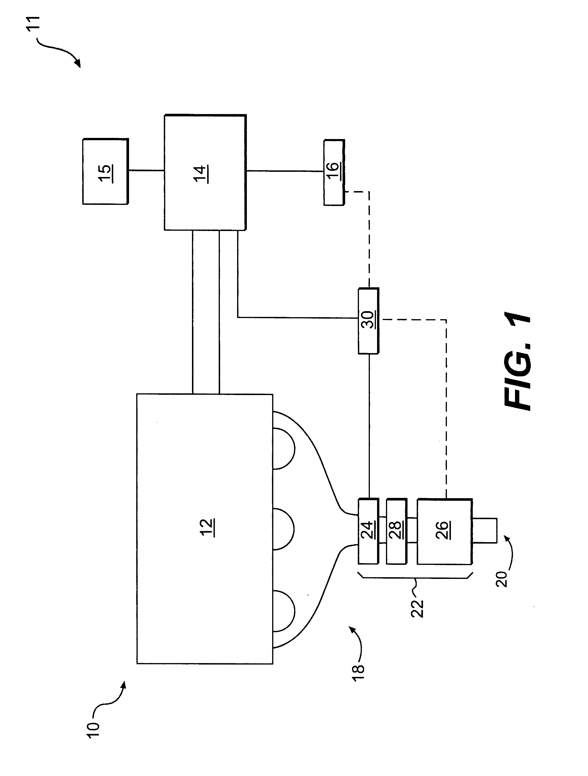
[0013]FIG. 1 provides a schematic representation of a machine 10 including a power source 12. Machine 10 can include a hybrid engine 11, wherein hybrid engine 11 can include power source 12 and an electric motor 15. As described herein, hybrid engine 11 can include various types and configurations of power source 12 and electric motor 15.

[0014]In some embodiments, power source 12 may include any type of internal combustion engine. For example, power source 12 could be configured to operate on any type of fuel, including diesel, gasoline, ethanol, gaseous fuel, bio-fuel, or any other fuel type or combination of fuels. Further, power source 12 may be configured to provide power to an on-highway vehicle, construction or mining equipment, a factory or power plant, or any other type of mobile or stationary machine known in the art.

[0015]Power source 12 can be operably associated with a generator 14 configured to convert mechanical energy into electric energy. In some embodiments, power s...


PUM


Abstract

A temperature control system is provided for use with a hybrid engine. The system includes a controller configured to receive a signal representative of a temperature associated with a selective catalytic reduction (SCR) catalyst configured to receive an exhaust gas stream produced by a hybrid engine. The controller is also configured to transmit a first signal to a generator operably coupled to a battery and the hybrid engine, and transmit a second signal to a heater configured to heat the SCR catalyst, wherein the first and second signals are configured to regulate the temperature associated with the SCR catalyst.

Description

TECHNICAL FIELD [0001]The present disclosure is directed to a temperature control system and, more particularly, to a catalyst temperature control system for a hybrid engine.BACKGROUND [0002]Hybrid engines typically include an electric motor and an internal combustion engine. Engines, including diesel engines, gasoline engines, gaseous fuel-driven engines, and other engines known in the art, traditionally exhaust a complex mixture of pollutants. These emissions may include gaseous and solid material, such as, particulate matter, nitrogen oxides (NOx), and sulfur compounds. Heightened environmental concerns have led regulatory agencies to increase the stringency of emission standards for such engines, forcing engine manufactures to develop systems to further reduce levels of engine emissions.[0003]Various devices and methods are used to reduce emission levels, including after-treatment devices such as nitrogen oxide absorbers, sulfur oxide absorbers, and hydrocarbon catalysts. These ...

Claims


Application Information

Patent Timeline
Patent Type & Authority Applications(United States)
IPC IPC(8): F01N3/021
CPCB60K6/485B60L2240/445B60W10/06B60W10/08B60W20/00B60W2510/068F01N3/023F01N3/0842F01N3/2013F02D41/024F02D2041/026F02D2200/0802Y02T10/54Y02T10/6226Y02T10/6286Y02T10/26Y02T10/24Y02A50/20Y02T10/12Y02T10/40Y02T10/62B60W2530/12
Inventor APPLEGATE, BRIAN C.EASLEY, JR., WILLIAM L.BOND, MICHAEL S.
Owner CATERPILLAR INC
Why Eureka
Try Eureka