Double gate manufactured with locos techniques

a technology of locos and double gates, which is applied in the direction of basic electric elements, electrical apparatus, and semiconductor devices, can solve the problems of gate oxide weakness, sgt) structure, and conventional dmos device gate to drain capacitance cgd by employing,

Inactive Publication Date: 2008-12-04
ALPHA & OMEGA SEMICON LTD
View PDF2 Cites 11 Cited by
  • Summary
  • Abstract
  • Description
  • Claims
  • Application Information

AI Technical Summary

Benefits of technology

[0007]It is therefore an aspect of the present invention to provide a new and improved semiconductor power device implemented with the split trenched-gates where the trenches are opened as a top portion and a bottom portion with the top portion slightly wider than the bottom portion. A thick oxide layer is first form on the sidewalls of the bottom potion thus forming a bird beak shaped layer when extending into the top portion of the sidewalls. The bird beak shaped layer thus preventing an over-etch into the oxide layer to prevent the top segment of polysilicon to extend into an over-etching pocket surrounding the bottom gate segment.
[0008]Specifically, it is an aspect of the present invention to provide improved device configuration and manufacturing method to reduce the gate to drain capacitance while accurately control the separation of the top and bottom gate segment by providing a manufacturing process and configuration that the over-etching pocket into the lower oxide layer is prevented by first forming a thick bottom oxide with a bird-beak shaped layer around the top portion of the bottom trench. Special LOCOS processes for forming the bottom thick oxide are applied to provide special advantages of a new structure to reduce Ciss, Coss and Crss to improve the efficiency of Power MOSFET. The new approach will enable the manufacturing process to eliminate the oxide dip back and in the same time to provide the flexibility of improve inter poly oxide to have better reliability.

Problems solved by technology

Conventional technologies for reducing the gate to drain capacitance Cgd in a DMOS device by employing the split trenched-gate, e.g., shielded gate trench (SGT) structure, are still confronted with technical limitations and difficulties.
However, as shown in FIG. 1, in the manufacturing process, a step of carrying out a wet etch of the first gate oxide often causes a problem of gate oxide weakness.
The oxide etch often extends below the top surface of the first polysilicon that have been first deposited into the bottom part of the trench thus causing the formation of an over-etching pocket.
Specifically, the sharp and thin inter-poly oxide causes early breakdown between source and gate due to the problems that 1) the dip leads to electric field concentration in the area that causes premature breakdown; and 2) the dip increases a gate-drain overlay thus the Cgd improvement is compromised.
Such technical difficulties become a problem when the conventional processes are applied.
This technical problem and performance limitation often become even more severe when the cell density is increased due to the shrinking dimension of the trench openings when forming the trenched power device in the semiconductor substrate.

Method used


Image

  • Double gate manufactured with locos techniques
  • Double gate manufactured with locos techniques
  • Double gate manufactured with locos techniques

Examples


Embodiment Construction

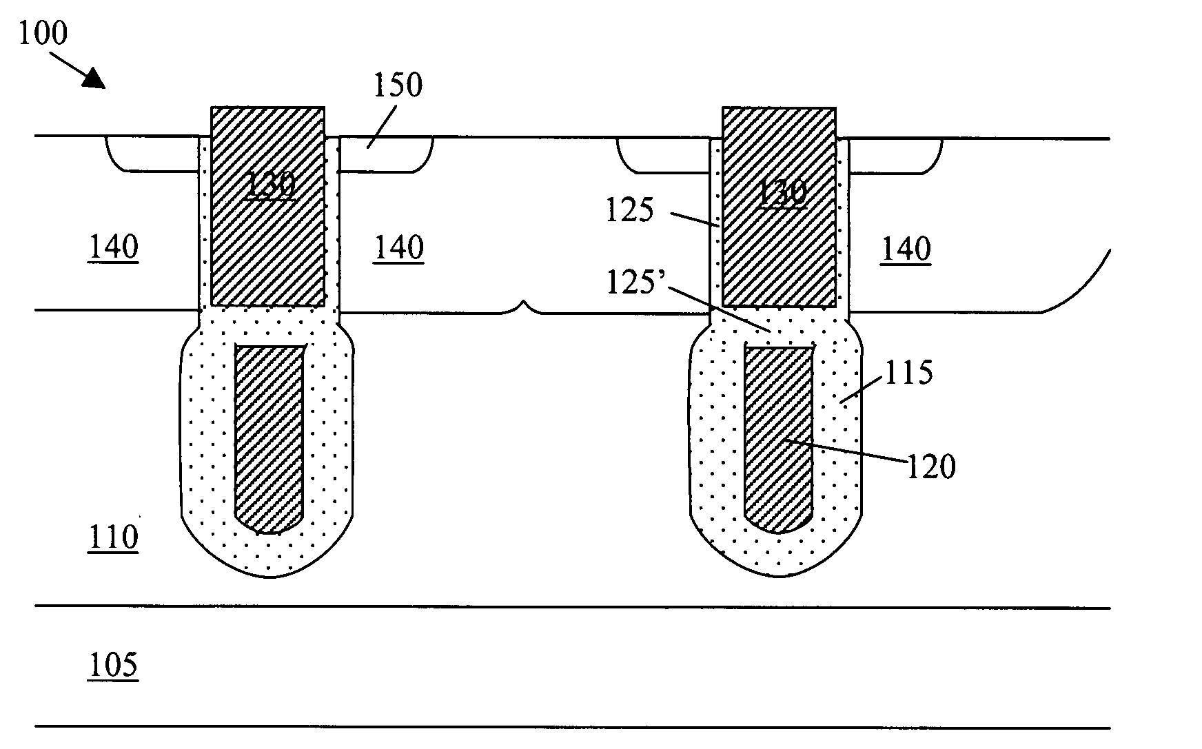
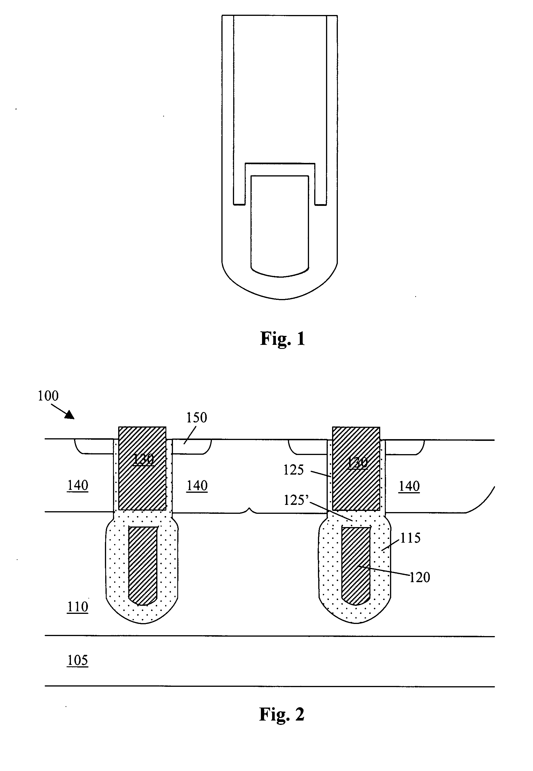
[0015]Referring to FIG. 2 for a cross sectional view of a trenched MOSFET device 100 of this invention. The trenched MOSFET device 100 is supported on a substrate 105 formed with an epitaxial layer 110. The trenched MOSFET device 100 includes a bottom gate segment 120 filled with polysilicon at the bottom portion below a top trenched gate segment 130. The bottom gate segment 120 filled with the polysilicon is shielded and insulated from a top gate polysilicon segment 130 by an insulation oxide layer 125′ disposed between the top and bottom segments. The bottom trenched-segment is also insulated from the drain disposed below 105 by the insulation layers 115 surrounding the bottom surface of the trenched gate. The top trenched gate segment 130 is also filled with polysilicon in the top portion of the trench surrounded with a gate insulation layer 125 covering the trenched walls.

[0016]A body region 140 that is doped with a dopant of second conductivity type, e.g., P-type dopant, extend...


PUM


Abstract

This invention discloses a trenched semiconductor power device that includes a trenched gate surrounded by a source region encompassed in a body region above a drain region disposed on a bottom surface of a substrate. The trenched gate further includes at least two mutually insulated trench-filling segments with a bottom insulation layer surrounding a bottom trench-filling segment having a bird-beak shaped layer on a top portion of the bottom insulation attached to sidewalls of the trench extending above a top surface of the bottom trench-filling segment.

Description

BACKGROUND OF THE INVENTION[0001]1. Field of the Invention[0002]The invention relates generally to the semiconductor power devices. More particularly, this invention relates to an improved and novel manufacturing process and device configuration for providing the semiconductor device with double gates by applying a LOCOS technique.[0003]2. Description of the Prior Art[0004]Conventional technologies for reducing the gate to drain capacitance Cgd in a DMOS device by employing the split trenched-gate, e.g., shielded gate trench (SGT) structure, are still confronted with technical limitations and difficulties. Specifically, trenched DMOS devices are configured with trenched gates wherein large capacitance (Cgd) between gate and drain limits the device switching speed. The capacitance is mainly generated from the electrical field coupling between the bottom of the trenched gate and the drain. In order to reduce the gate to drain capacitance, an improved split trenched-gate configuration,...

Claims


Application Information

Patent Timeline
Patent Type & Authority Applications(United States)
IPC IPC(8): H01L29/94H01L21/336
CPCH01L29/407H01L29/42368H01L29/66734H01L29/7813
Inventor TAI, SUNG-SHANHU, YONGZHONG
Owner ALPHA & OMEGA SEMICON LTD
Why Eureka
Try Eureka