Radio Frequency Device with Magnetic Element, Method for Making Such a Magnetic Element

a radio frequency device and magnetic element technology, applied in the direction of magnetic layers, ultrathin/granular films, ion implantation coatings, etc., can solve the problems of discontinuous magnetic circuits, high cost, and high cost, and achieve the effect of simple (linear) control of the anisotropy reinforcement

Inactive Publication Date: 2008-12-04
STMICROELECTRONICS SRL +1
View PDF6 Cites 104 Cited by
  • Summary
  • Abstract
  • Description
  • Claims
  • Application Information

AI Technical Summary

Benefits of technology

[0024]In the case of a process using an external abrasive source, such as an ion gun for the ion-beam sputtering, or a laser for laser ablation, the directionality of the emission of material also allows the angle between the direction of material flux and the normal to the target to be adjusted. The direction of the magnetic field is preferably orthogonal to the direction of the axes about which the abrasive source, the target, and the substrate are pivotable. This allows anisotropy directions of the material that are, on the one hand, induced by the field during the deposition process and, on the other hand, due to the inclination of the grains, are collinear, which allows a direct cumulative effect and simple (linear) control of the anisotropy reinforcement effect.

Problems solved by technology

Currently, for radiofrequency applications, such devices generally only use discontinuous magnetic circuits.
Under these conditions, the ferromagnetic resonance frequency, which forms the upper limit for the dynamic application of these materials, remains too low (˜2 GHz) with regard to the targeted applications, notably telephones.
These are therefore discontinuous magnetic circuits whose main difficulty is related to the optimization of the ratio between the width of the magnetic element and the separation distance between magnetic elements.
This is made all the more difficult if it is desired to close the magnetic flux in order to obtain a better electromagnetic confinement around the inductive element (sandwiched spiral or toroidal solenoid).
Consequently, by virtue of the requirement for a discontinuous nature of the magnetic element itself and by virtue of the impossibility of forming a closed-flux circuit, it is not currently possible to reconcile an increase in the ferromagnetic resonance frequency of the magnetic element with the optimization of the electromagnetic confinement around the inductive element.
Consequently, this results in components with diminished performance (low gain over L˜10% and reduced Q<10 at 1 GHz) that are unusable for the desired application (RF circuits).

Method used


Image

  • Radio Frequency Device with Magnetic Element, Method for Making Such a Magnetic Element
  • Radio Frequency Device with Magnetic Element, Method for Making Such a Magnetic Element
  • Radio Frequency Device with Magnetic Element, Method for Making Such a Magnetic Element

Examples


Embodiment Construction

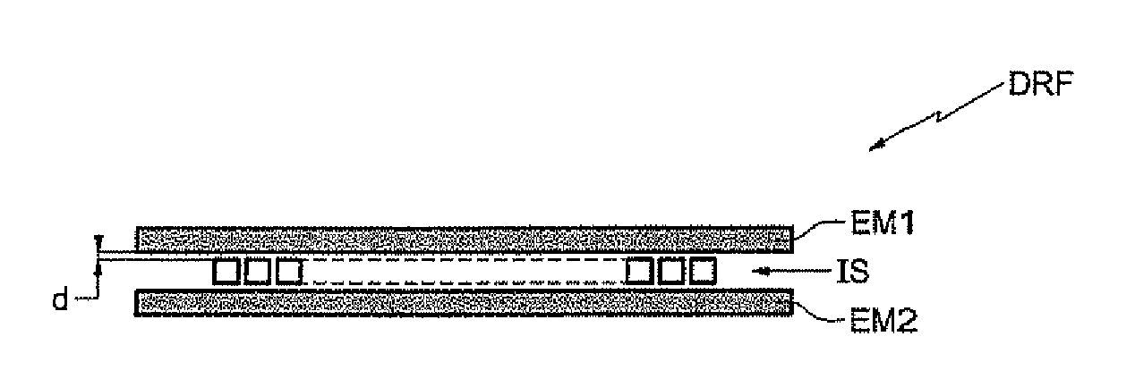
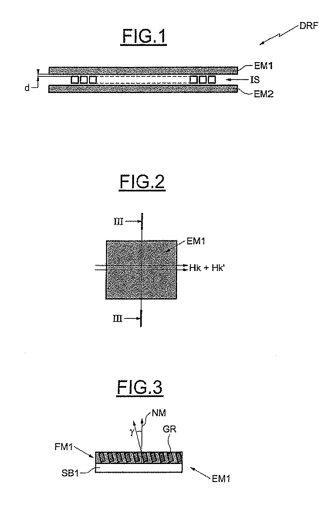
[0032]In FIG. 1, the reference DRF denotes a radiofrequency device according to an embodiment of the invention comprising a conducting element IS formed from a spiral coil sandwiched between a first magnetic element EM situated on top of the coil IS and a second magnetic element EM2 is situated underneath the coil. The two magnetic elements are continuous elements and are advantageously separated from the conducting element IS by a relatively small distance d. This distance d is, for example, less than or equal to 5 μm. The configuration of the device DRF allows a virtually-closed magnetic circuit to be obtained using continuous magnetic elements.

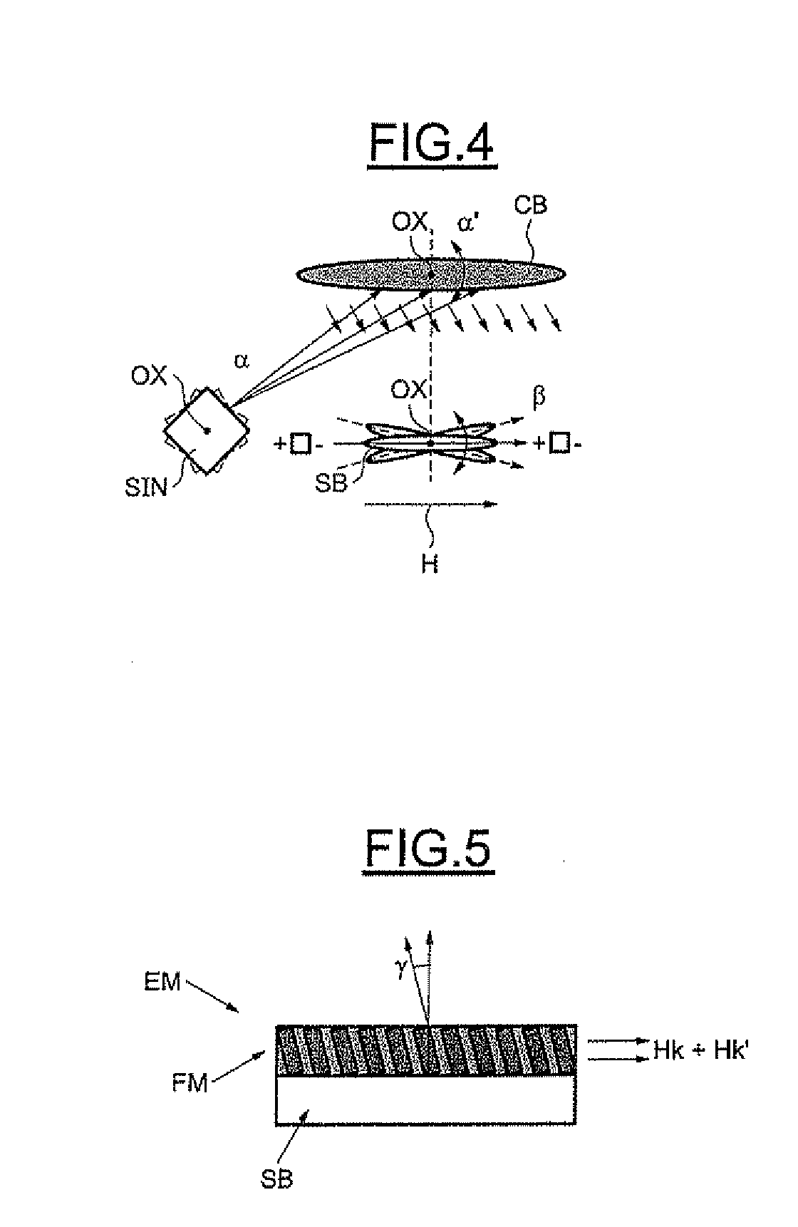
[0033]As is illustrated more particularly in FIGS. 2 and 3, each magnetic element EM1 comprises a substrate SB1 coated with a continuous granular magnetic film SM1 whose grains exhibit an oblique orientation to the normal NM to the substrate SB1. The orientation angle γ is, for example, around 60° and may, more generally, be in the range fr...


PUM

PropertyMeasurementUnit
angle of inclinationaaaaaaaaaa
ferromagnetic resonance frequencyaaaaaaaaaa

Abstract

A radiofrequency device may include an electrically conducting element associated with at least one continuous magnetic element. The first continuous magnetic element may include a substrate coated with a magnetic film having a granular structure, with grains that are inclined to the normal to the substrate, or a columnar texture inclined to the normal of the substrate.

Description

FIELD OF THE INVENTION[0001]The invention relates to radiofrequency devices comprising a conducting element associated with a magnetic element, in particular, radiofrequency inductive elements, but also, for example, radiofrequency filters or resonators.BACKGROUND OF THE INVENTION [0002]Currently, for radiofrequency applications, such devices generally only use discontinuous magnetic circuits. In other words, the radiofrequency applications include a plurality of elementary parts with finite dimensions because of a limitation that is intrinsic to soft magnetic materials.[0003]Indeed, these materials generally must be of an anisotropic nature characterized by a field called an anisotropy field (Hk) whose principal origin is associated with a preferential chemical ordering at the scale of the crystal lattice. This effect is generally obtained by conventional deposition of the material, by a plasma or electrochemical means, in the presence of an applied magnetic field. It is an intrins...

Claims


Application Information

Patent Timeline
Patent Type & Authority Applications(United States)
IPC IPC(8): H01F10/12C23C14/46C23C14/35
CPCB82Y25/00H01F10/007H01F10/147H01F10/16H01F41/18H01F41/205H01F2017/0066H01P1/215
Inventor VIALA, BERNARDCOUDERC, SANDRINEANCEY, PASCAL
Owner STMICROELECTRONICS SRL
Why Eureka
Try Eureka