System and method for locating a three-dimensional object using machine vision

a machine vision and object technology, applied in the field of machine vision systems, can solve the problem that the single affine transformation cannot be trusted to provide the registered pattern, and achieve the effect of minimizing the total error and minimizing the error

Active Publication Date: 2008-12-04
COGNEX CORP
View PDF99 Cites 59 Cited by
  • Summary
  • Abstract
  • Description
  • Claims
  • Application Information

AI Technical Summary

Benefits of technology

[0009]This invention overcomes the disadvantages of the prior art by providing a system and method for determining position of a viewed object in three dimensions by employing 2D machine vision processes on each of a plurality of planar faces (or other portions of the image object image that can rotate with the origin and be divided into edgelets) of the object, and thereby refining the location of the object. The object can be at a previously unknown location and orientation or can be at a relatively known location (e.g. on the end effector of a robot that includes position feedback). First a rough pose estimate of the object is derived. This rough pose estimate can be based upon (for example) location data for an end effector holding the object, a comparison of the acquired object image to a table of possible silhouettes of the trained object in different orientations, or by acquiring...

Problems solved by technology

There are a number of challenges to registering an object in three-dimensions from trained images using this approach.
For example, when non-coplanar object features are imaged...

Method used


Image

  • System and method for locating a three-dimensional object using machine vision
  • System and method for locating a three-dimensional object using machine vision
  • System and method for locating a three-dimensional object using machine vision

Examples


Embodiment Construction

[0024]I. Calibration of the Cameras

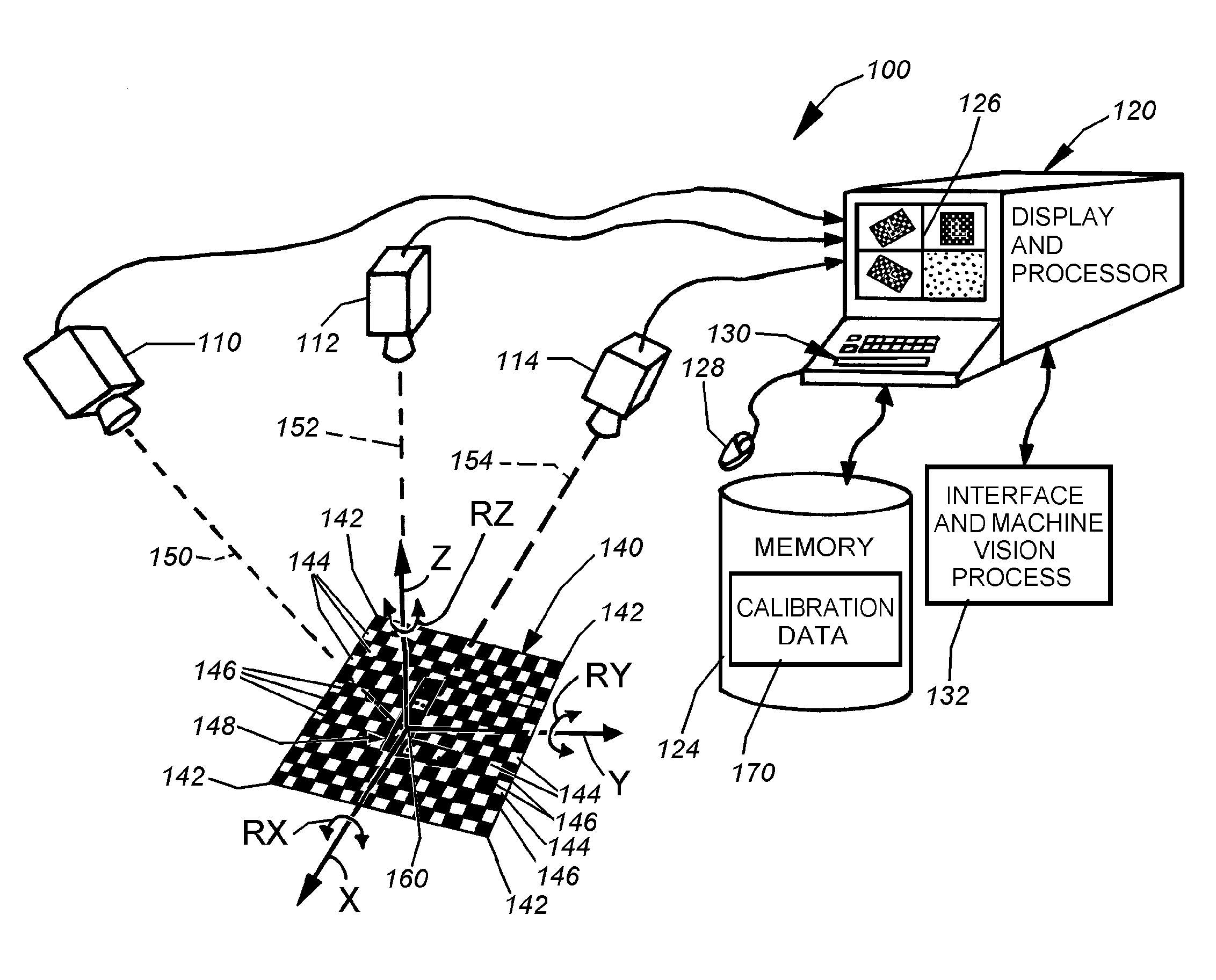
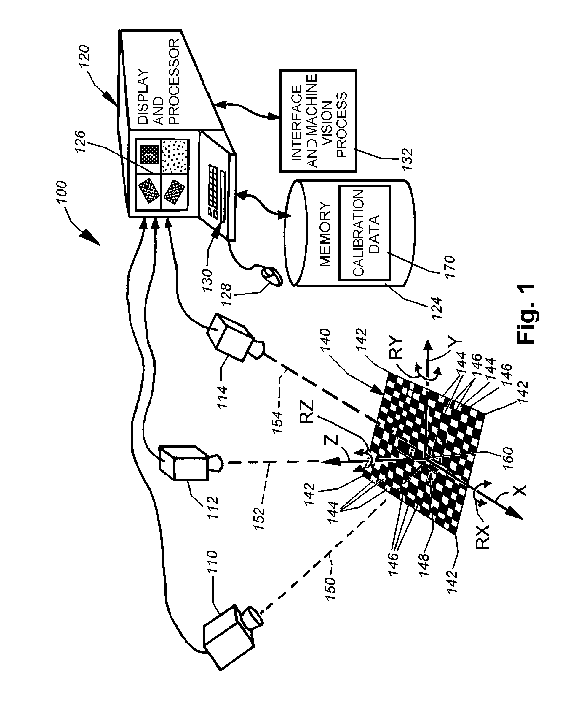
[0025]FIG. 1 details an exemplary setup for a machine vision system 100 capable of registering objects in three dimensions (3D) using six degrees of freedom (three translational degrees and three rotational degrees). The system 100 includes a plurality of cameras 110, 112 and 114 in this embodiment that are each oriented to derive a different view of an underlying subject. The number of cameras and their positioning with respect to a subject is highly variable. In alternate embodiments, only two camera's can be employed, or even a single camera with a sufficiently wide field of view, and some inherent distortion (for example a camera equipped with a fish-eye lens) so that, either, at least two discrete poses of a subject can be derived from a single image (if no coarse pose estimate is supplied) or at least four features on the image occur along non-parallel rays (described below) from the camera (if a coarse pose estimate is supplied). For the pur...


PUM


Abstract

This invention provides a system and method for determining position of a viewed object in three dimensions by employing 2D machine vision processes on each of a plurality of planar faces of the object, and thereby refining the location of the object. First a rough pose estimate of the object is derived. This rough pose estimate can be based upon predetermined pose data, or can be derived by acquiring a plurality of planar face poses of the object (using, for example multiple cameras) and correlating the corners of the trained image pattern, which have known coordinates relative to the origin, to the acquired patterns. Once the rough pose is achieved, this is refined by defining the pose as a quaternion (a, b, c and d) for rotation and a three variables (x, y, z) for translation and employing an iterative weighted, least squares error calculation to minimize the error between the edgelets of trained model image and the acquired runtime edgelets. The overall, refined/optimized pose estimate incorporates data from each of the cameras' acquired images. Thereby, the estimate minimizes the total error between the edgelets of each camera's/view's trained model image and the associated camera's/view's acquired runtime edgelets. A final transformation of trained features relative to the runtime features is derived from the iterative error computation.

Description

FIELD OF THE INVENTION[0001]This invention relates to machine vision systems, and more particularly to machine vision systems that locate viewed objects having three-dimensional characteristics.BACKGROUND OF THE INVENTION[0002]The use of advanced machine vision systems and their underlying software is increasingly employed in a variety of manufacturing and quality control processes. Machine vision enables quicker, more accurate and repeatable results to be obtained in the production of both mass-produced and custom products. Typical machine vision systems include one or more cameras (typically having solid-state charge couple device (CCD) or CMOS-based imaging elements) directed at an area of interest, a frame grabber / image processing elements that capture and transmit CCD images, a computer or onboard processing device, and a user interface for running the machine vision software application and manipulating the captured images, and appropriate illumination on the area of interest....

Claims


Application Information

Patent Timeline
IPC IPC(8): G06K9/00G06K9/62G06V10/24
CPCG06K9/32G06T7/0042G06T2207/30164G06T7/73G06V10/24
Inventor WALLACK, AARON S.MICHAEL, DAVID J.
Owner COGNEX CORP
Why Eureka
Try Eureka