
Extrusion cutting apparatus

a cutting apparatus and cutting technology, applied in the direction of auxillary cutting apparatus, ceramic shaping apparatus, manufacturing tools, etc., can solve the problems of adversely affecting a chemical reaction, the size of the catalyst can affect the reaction rate, so as to improve the durability of the die plate and/or the extruder/die insert, improve the ease of use of the extruder/die, and improve the throughput of the extruder

Inactive Publication Date: 2008-12-04
JMP INDS
View PDF57 Cites 6 Cited by
  • Summary
  • Abstract
  • Description
  • Claims
  • Application Information

AI Technical Summary

Benefits of technology

[0008]The present invention relates to extrusion hardware, and more particularly to die plates, extruder die inserts, and cutting devices for use in an extruder system. In one non-limiting embodiment of the invention, there is provided specially designed extruder die inserts and die plates that can to used to extrude a wide variety of different materials. The extruder / die inserts and die plates of the present invention are designed to improve the throughput by an extruder, improve the durability of the die plate and / or extruder / die insert, improve the ease of use of the extruder / die insert in combination with the die plate, and / or improve the quality of the material extruded by the extruder system. In yet another and / or alternative non-limiting embodiment of the invention, there is provided a cutting assembly to cut materials that have been extruded through one or more extruder / die inserts that are positioned in a die plate. The extrusion hardware of the present invention is particularly directed to the extrusion and cutting of an extruded catalyst; however, the extrusion hardware can be used to cut many other types of extruded material.
[0009]In one non-limiting aspect of the present invention, there is provided a cutting assembly that is designed to cut materials on one or more types of materials that have been extruded through one or more die plates that may or may not include one or more extruder / die inserts. The improved cutting assembly is designed to improve the product quality of cut extruded material by cutting the extruded material within low tolerances to a certain specified length. In many types of businesses such as, but not limited to, the catalyst business, etc., the size of the extruded material must be maintained to comply with certain criteria. For instance, the size of the catalyst can affect the rate of reaction that takes place when using the catalyst. An extruded catalyst that is cut too large or too small could adversely affect a chemical reaction that involves the use of the catalyst. The proper cutting of other materials (e.g., foods, fertilizers, etc.) can affect the product quality and / or effectiveness of the cut product. The improved cutting assembly of the present invention is designed to cut an extruded product from a die plate to form a cut product that more closely matches the desired length of the product. In addition, the improved cutting assembly of the present invention can be used to cut products that are currently extruded through die plates and thereby significantly reduce the amount of waste of such extruded product that historically has to be disposed of since the extruded product did not meet the size tolerance parameters of the extruded product. As such, one non-limiting aspect of the present invention is thus directed to an extrusion cutting assembly which can increase the quantity of cut product.
[0010]In another and / or alternative non-limiting embodiment of the invention, the cutting assembly of the present invention includes a fluid cutting arrangement to cut and / or break material that is extruded through a die plate and / or one or more extruder / die inserts in a die plate. The fluid can be a liquid and / or a gas. In one non-limiting embodiment of the invention, the fluid is a gas. Non-limiting gasses include, but are not limited to, air, nitrogen, stream, noble gasses, etc. In another and / or alternative non-limiting embodiment of the invention, a high pressure fluid is at least partially used to cut and / or break material that is extruded through a die plate and / or one or more extruder / die inserts in a die plate. As defined in herein, high pressure is a pressure of about 20 psig or greater. In one non-limiting aspect of this embodiment, the high pressure fluid used by the cutting assembly of the present invention is at least about 25 psig. In another and / or alternative non-limiting aspect of this embodiment, the high pressure fluid used by the cutting assembly of the present invention is at least about 50 psig. In still another and / or alternative non-limiting aspect of this embodiment, the high pressure fluid used by the cutting assembly of the present invention is at least about 60 psig. In still yet another and / or alternative non-limiting aspect of this embodiment, the high pressure fluid used by the cutting assembly of the present invention is less than about 10,000 psig. In another and / or alternative non-limiting aspect of this embodiment, the high pressure fluid used by the cutting assembly of the present invention is less than about 1,000 psig. In still another and / or alternative non-limiting aspect of this embodiment, the high pressure fluid used by the cutting assembly of the present invention is less than about 500 psig. In still another and / or alternative non-limiting aspect of this embodiment, the high pressure fluid used by the cutting assembly of the present invention is less than about 200 psig. In still another and / or alternative non-limiting embodiment of the invention, a super heated steam can be used solely as the high pressure fluid or be combined with one or more other high pressure fluids (e.g., air, noble gas, etc.). The super heated steam is defined as steam having a temperature of over 110° C., generally over about 150° C., typically at least about 200° C., and more typically at least about 250° C. As can be appreciated, higher temperature super heated steam can be used. The super heated steam, when used, can be used to facilitate in the drying of the material that is extruded through a die plate and / or one or more extruder / die inserts in a die plate. The super heated steam can also or alternatively be used to increase the PV and / or CS of the material that is extruded through a die plate and / or one or more extruder die inserts in a die plate.

Problems solved by technology

For instance, the size of the catalyst can affect the rate of reaction that takes place when using the catalyst.
An extruded catalyst that is cut too large or too small could adversely affect a chemical reaction that involves the use of the catalyst.

Method used


Image

  • Extrusion cutting apparatus
  • Extrusion cutting apparatus
  • Extrusion cutting apparatus

Examples


Embodiment Construction

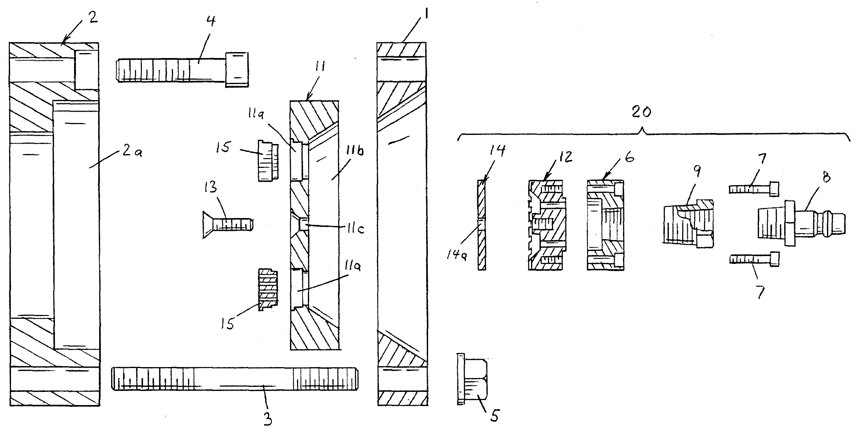
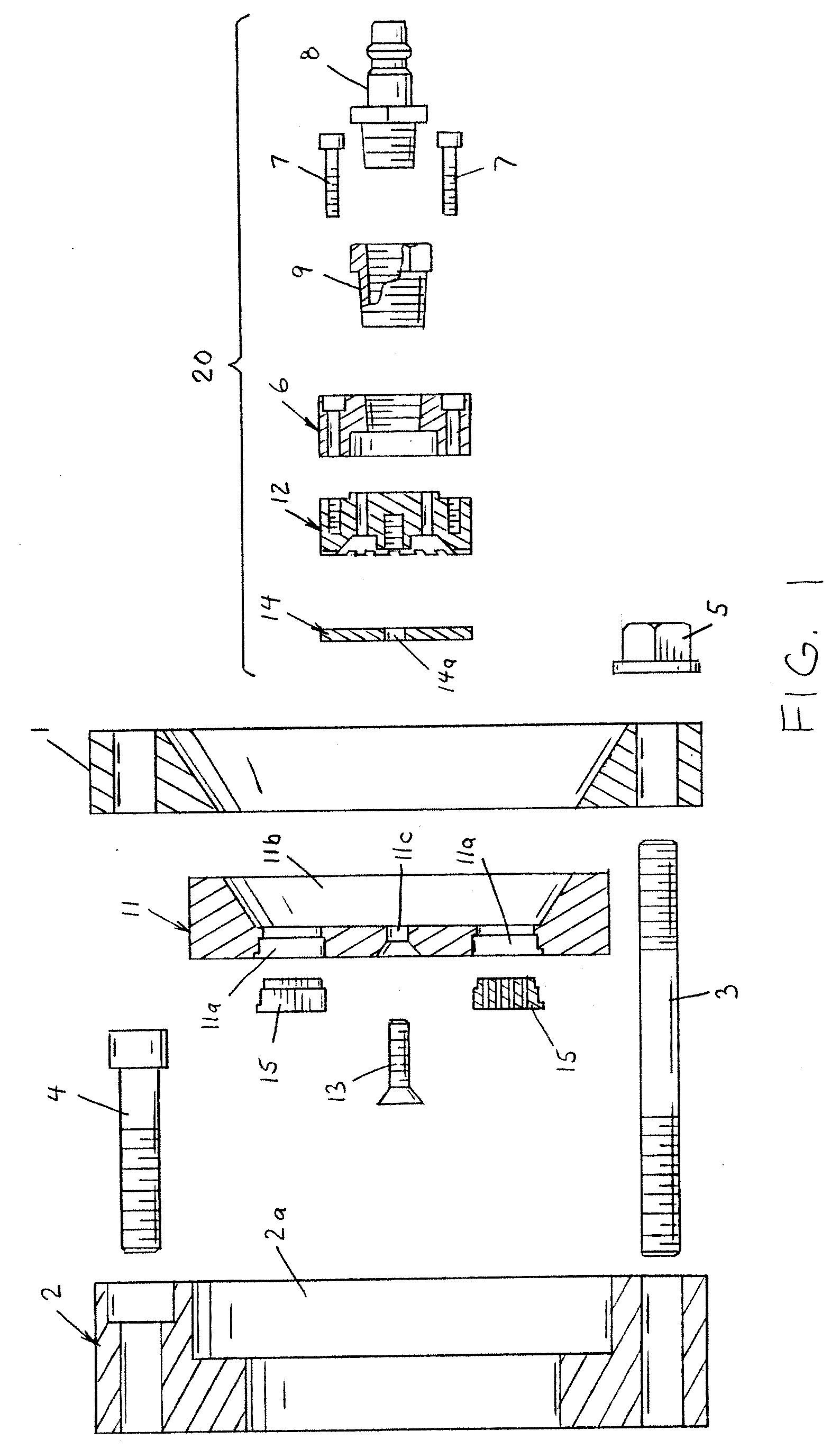
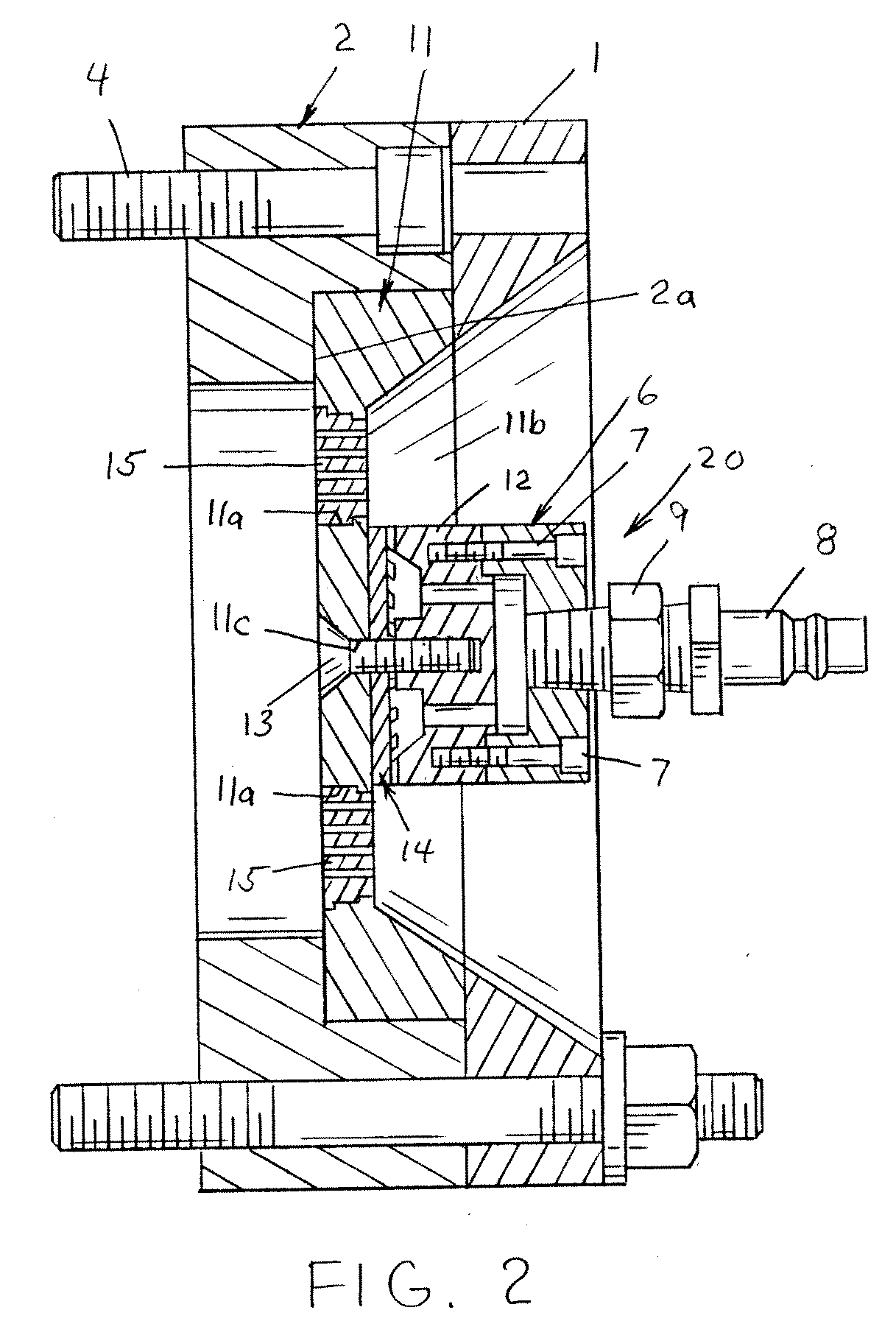
[0037]Referring now to the drawings wherein the showing is for the purpose of illustrating preferred embodiments of the invention only and not for the purpose of limiting the same,FIGS. 1 and 2 illustrate non-limiting configurations of a portion of an extruder system and the cutting assembly in accordance with the present invention. Specifically, FIG. 1 illustrates a cross-section view of a die holder 2, that is designed to receive a cutting assembly 20, which cutting assembly is designed to be secured to a die plate 11. Die holder 2 can be connected to the head of any type of extruder by use of one or more screws 4 as illustrated in FIG. 2. As can be appreciated, the die holder can be connected to the extruder in other or additional arrangements. Die plate 11 is designed to fit into a cavity 2a in die holder 2. This is best illustrated in FIG. 2. A clamping ring 1 is designed to be secured to the die holder by one or more threaded studs 3 and bolts 5 as illustrated in FIGS. 1 and 2...


PUM


Abstract

An extruder system and a cutting assembly for cutting a material extruded from a die plate.

Description

[0001]The present invention claims priority on U.S. Provisional Application Ser. No. 60 / 932,295 filed May 30, 2007 entitled “Extrusion Cutting Apparatus”, all of which is incorporated herein by reference.[0002]The present invention also claims priority on U.S. Provisional Application Ser. No. 60 / 961,081 filed Jul. 18, 2007 entitled “Extrusion Cutting Apparatus”, all of which is incorporated herein by reference.[0003]The present invention relates to extrusion hardware, and more particularly to die plates, die plate inserts and cutting devices for use in an extruder system.INCORPORATION BY REFERENCE[0004]The following patents and patent applications are incorporated herein by reference to provide background information relating to extruder technology and can be used in and, or with the present invention, namely U.S. Pat. Nos. D442,612; D444,487; D446,794; D450,732; D452,257; D469,116; D469,117; D469,452; D469,453; D469,454; D470,869; D470,870; D472,252; D485,286; D494,198; D496,377: D...

Claims


Application Information

Patent Timeline
IPC IPC(8): B29C47/92B29C48/92
CPCB29B9/06B29C47/003B29C47/92B29C2793/0027B29C47/0066B29C48/92B29C2948/92704B29C48/12B29C48/0022B29C2948/92514B29C2948/92638B29C2948/92904
Inventor PINCHOT, JAMES M.
Owner JMP INDS
Learn More