Parallel integrated bioreactor device and method

Active Publication Date: 2008-12-04
MASSACHUSETTS INST OF TECH
View PDF0 Cites 45 Cited by
  • Summary
  • Abstract
  • Description
  • Claims
  • Application Information

AI Technical Summary

Benefits of technology

[0010]The present invention addresses the need for a scalable, easy to use, bioreactor system capable of performing multiple bacteria or cell growth experiments under controlled conditions, and to high cell densities, among other things. In various embodiments, the method and apparatus of the present invention introduces integrated fluid injection and mixing devices to enable dissolved oxygen and/or pH control in a miniature parallel integrated bioreactor device, and i

Problems solved by technology

One significant challenge is to carry out large numbers of experiments rapidly and effectively.
For example, screening of different strains is often conducted in microtiter plates, under relatively uncontrolled conditions and with only limited possibility of monitoring conditions during culture.
Such flasks typically allow only partial control over important environmental variables and cannot achieve the high oxygen (O2) concentrations typically used in large-scale fermentation processes.
Thus the usefulness of these open loop systems for selecting the organism that will be optimal under actual bioprocess conditions is limited.
However, bench-scale reactors, with typical volumes of between 0.5 and 10 liters suffer from a number of drawbacks.
Because of their large size, relatively high cost, and the time and effort required to obtain the data it is typically not practical to test as many combinations of strains and environmental conditions as would be desirable.
However, these systems require expensive pipetting robotics and careful sterilization of the pipette tips to prevent contaminati

Method used


Image

  • Parallel integrated bioreactor device and method
  • Parallel integrated bioreactor device and method
  • Parallel integrated bioreactor device and method

Examples


example 1

Materials And Methods

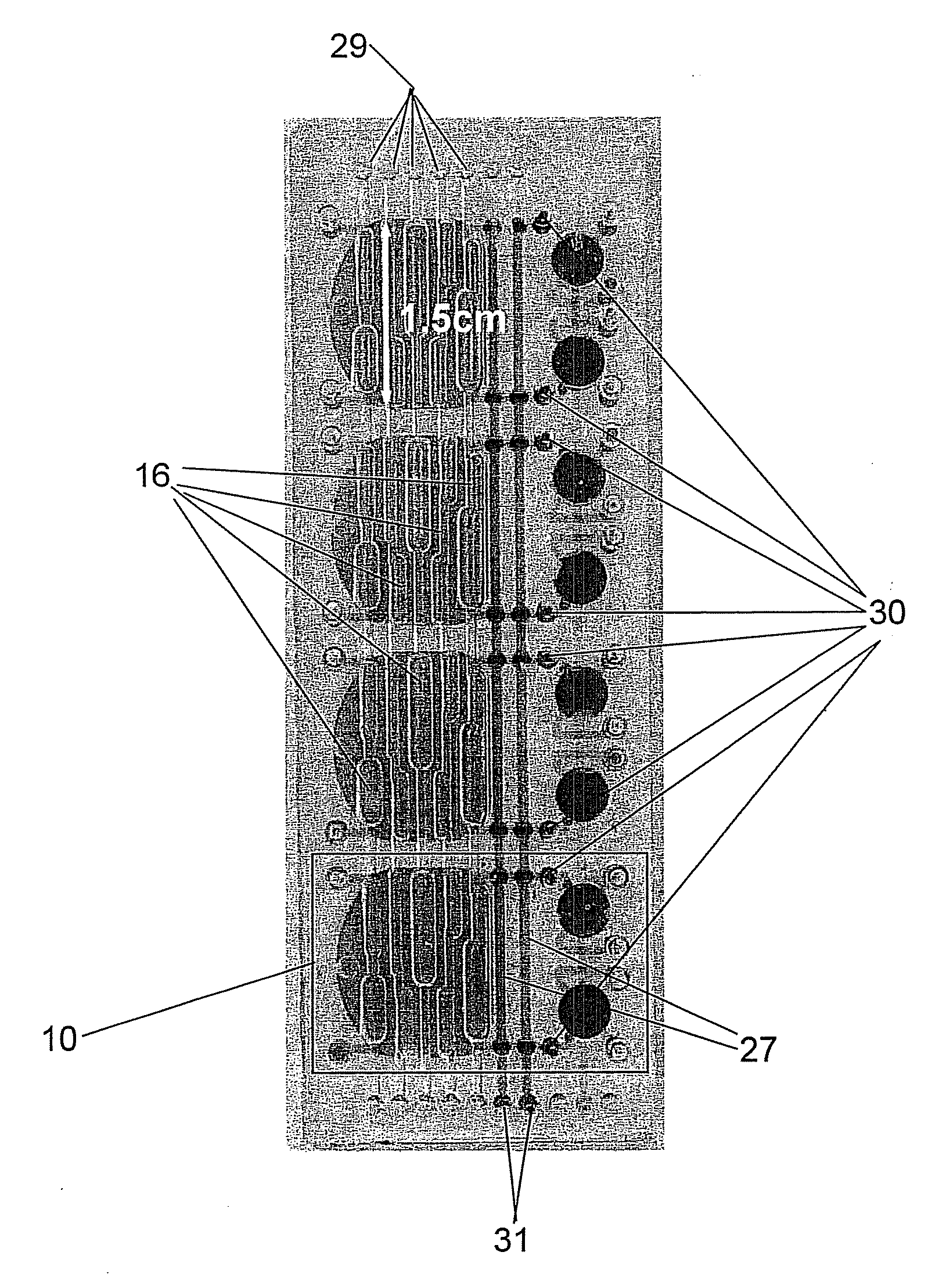
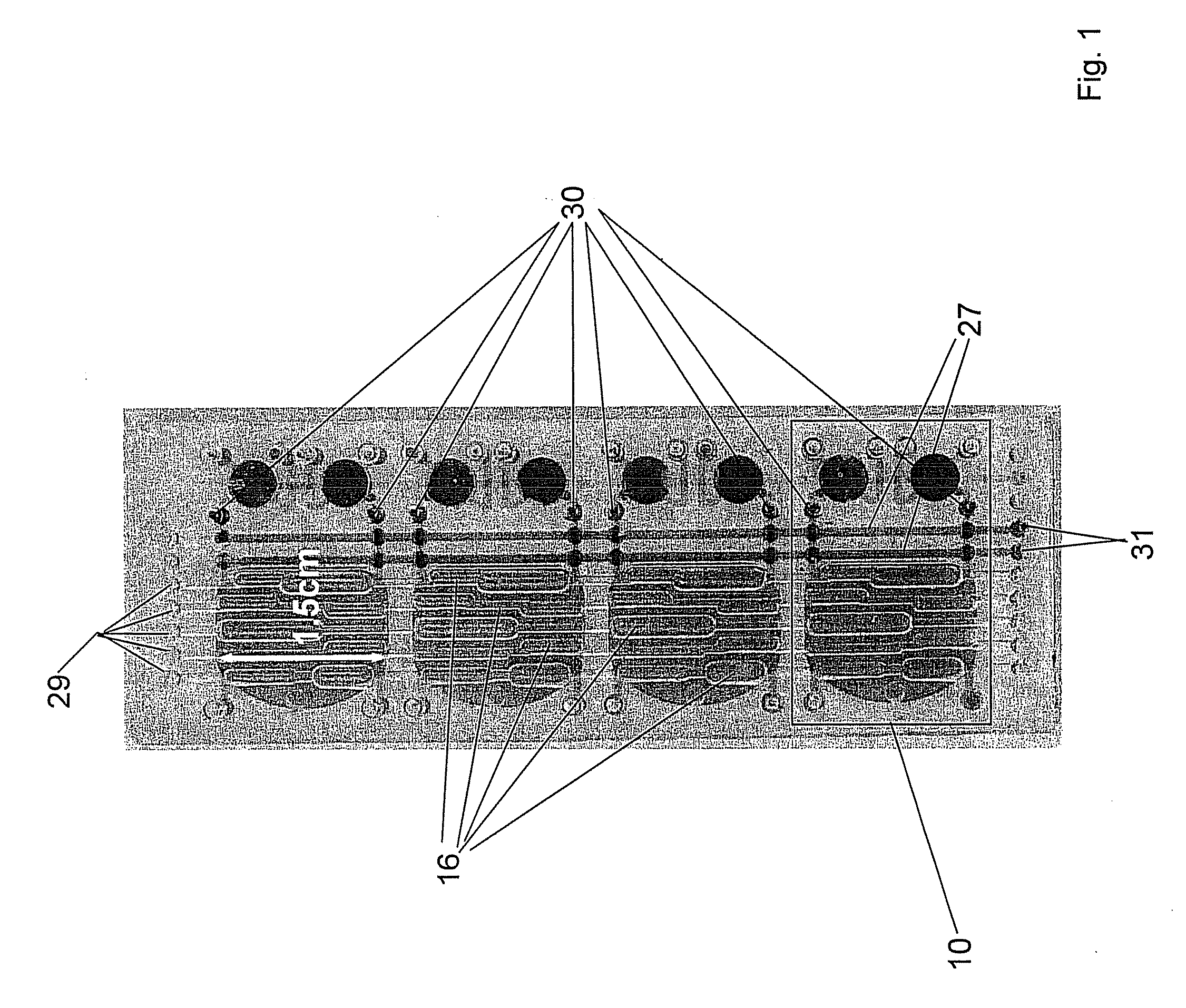
[0116]Using the device as shown in FIG. 1, four sulfite oxidation experiments were run simultaneously wherein the pH control was activated only in two reactors. The device was mounted into an interface module and the fluid injector actuation lines were activated. Approximately 20 μL of 1M HCL was injected into the acid reservoir, and 20 μL of 1M NaOH was injected into the base reservoir, using a syringe and fine gauge needle. The acid / base lines were primed such that a small amount of acid / base was injected into the empty reservoirs. An identical solution of 100 mM of sodium sulfite in 100 mM dibasic phosphate was injected into all four reactors via a syringe and fine gauge needle. Since sulfite is a weak base with pKa=6.8, it has a buffering capacity of around neutral pH. When sulfite is oxidized into sulfate, the buffer capacity is lost and the pH decreases. The peristaltic oxygen mixers were activated in each of the bioreactors. Before the solutions were inje...

example 2

Materials And Methods

[0118]Using the device shown in FIG. 1, reactors were run wherein fluid injections supplied acid and base to the growth chamber (filled with 100 mM phosphate buffer), and a pH sensor measured the pH of the growth chamber after each injection. The first reactor received an injection of 270 nL acid (1M HCl) and base (1M NaOH) every two minutes for two hours.

Results

[0119]FIG. 4a shows pH versus time wherein the markers indicate the pH measurement after every second pH injection. FIG. 4b is a zoom view of a portion of the pH versus time graph shown in FIG. 4a. FIG. 4b shows that the injected base is mixed into the growth chamber within fifteen seconds. This is indicated by the sharp steps in pH after each injection. The markers of FIG. 4 indicate every other acid or base injection. FIG. 4c shows agreement with a direct alignment with a conventionally measured titration curve, verifying the accuracy of the estimated injected volume (e.g., 270 nL). Aligning this titra...

example 3

Materials And Methods

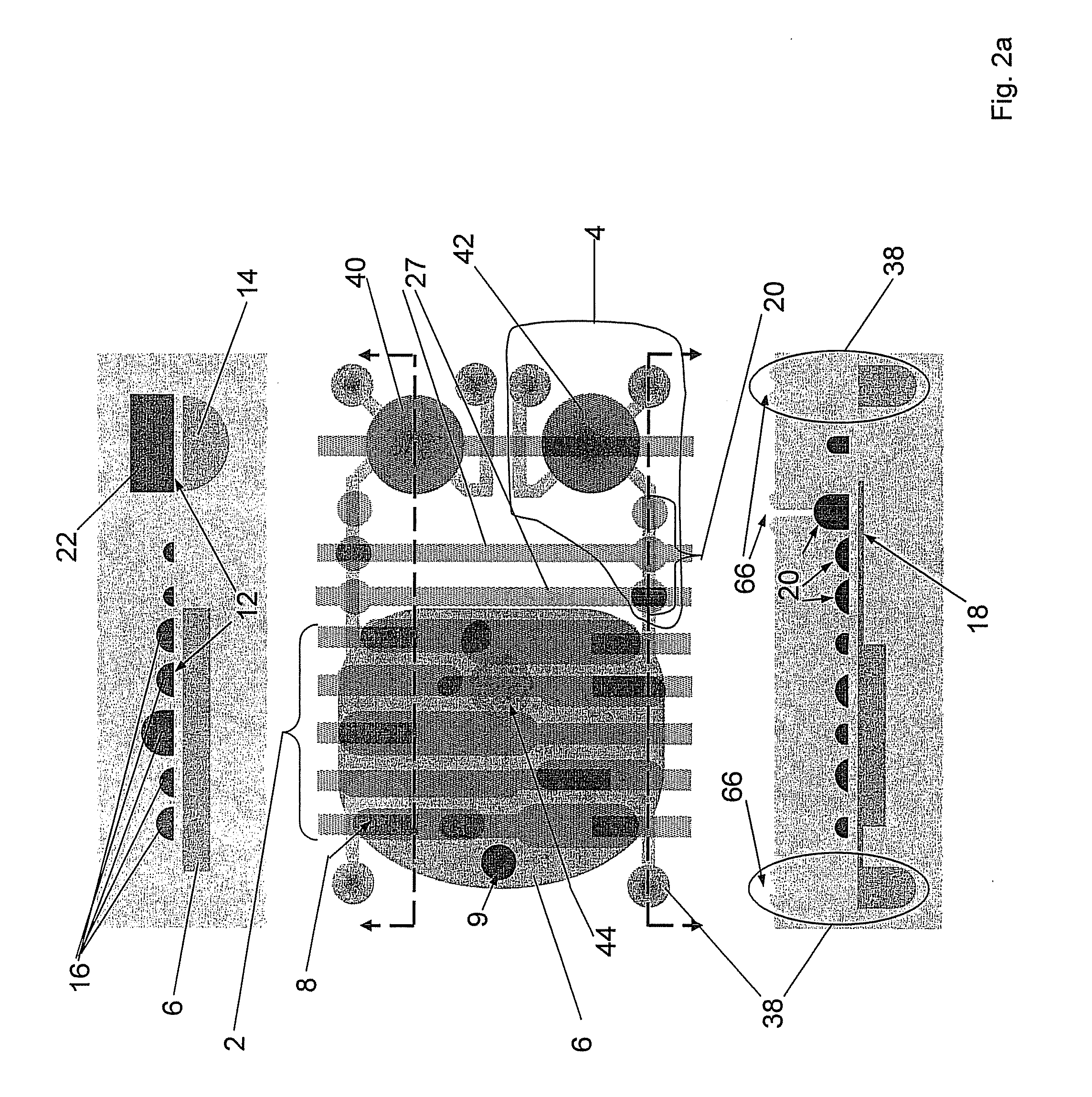
[0120]The fluid injectors shown in FIGS. 1 and 2 consist of a 16 μL hemispherical fluid reservoir sealed with a flexible membrane, which can be deflected by pressurizing the chamber above, and an injector channel gated by three pneumatically actuated membrane pinch valves, which meter the fluid. Pressurizing the fluid reservoirs served to help open the pinch valves and ensure injection against backpressure. The mixing tubes and pinch valves were actuated pneumatically as described above, and the mixing tubes and two metering valves are shared for the economy of the pneumatic switches.

[0121]Mixing was accomplished by approximating peristalsis in the 85 μL growth wells by pressurizing the mixing tubes two at a time in a propagating pattern, generating a circulating flow across and around the well.

[0122]The devices were fabricated using two molded PDMS (Dow Corning, Sylgard 184) layers and a 70 μm thick PDMS membrane, bonded with a partial cure bond. Master positiv...


PUM


Abstract

In one embodiment, the present invention introduces integrated fluid injection and mixing devices to enable pH control in a miniature parallel integrated bioreactor array system. In another embodiment, the environmental conditions of the growth chamber is enabled through fluidic injections in a miniature parallel cell culture system. In still another embodiment, the present invention utilizes gas switches to control oxygen concentration within a miniature parallel integrated bioreactor array.

Description

PRIORITY INFORMATION[0001]This application is related to the subject matter in U.S. provisional application Ser. No. 60 / 724,971, filed Oct. 7, 2005; U.S. provisional application 60 / 780,982, filed Mar. 10, 2006; U.S. provisional application Ser. No. 60 / 376,711, filed May 1, 2002; U.S. utility application Ser. No. 10 / 717,409, filed Nov. 18, 2003; and U.S. provisional application Ser. No. 60 / 613,140, filed Sep. 24, 2004. The entire contents of each of these applications are incorporated herein by reference. It is noted that certain information and / or data in the instant specification may supersede information and / or data in the earlier applications, in which case the instant specification will control.BACKGROUND OF THE INVENTION[0002]A critical driving force behind research in bioprocess science and engineering continues to be the demand for fast and accurate analytical information that can be used, for example, to evaluate the interactions between biological systems and bioprocess ope...

Claims


Application Information

Patent Timeline
IPC IPC(8): C12M3/00C12M3/06C12M1/36C12Q3/00C12N1/20C12Q1/02
CPCB01F11/0045C12M29/26B01F2215/0431B01F2215/0454B01L3/5025B01L3/5027B01L3/50273B01L3/502738B01L7/00B01L2300/0867B01L2300/10B01L2400/0487C12M23/16C12M23/22C12M23/44C12M29/14C12M33/07C12M41/26C12M41/34C12M41/40C12M27/02C12M23/40B01F13/0059B01F31/31B01F33/30
Inventor LEE, HARRYRAM, RAJEEVJENSEN, KLAVS
Owner MASSACHUSETTS INST OF TECH
Why Eureka
Try Eureka