

Semiconductor device and display device
a display device and semiconductor technology, applied in non-linear optics, instruments, optics, etc., can solve the problems of large area, complicated wiring between tfts, and ineffective multi-layer technology, so as to reduce the arrangement area required, the ground voltage rises drastically, and the arrangement area is reduced.
- Summary
- Abstract
- Description
- Claims
- Application Information
AI Technical Summary
Benefits of technology
Problems solved by technology
Method used
Image

Examples
embodiment mode 1
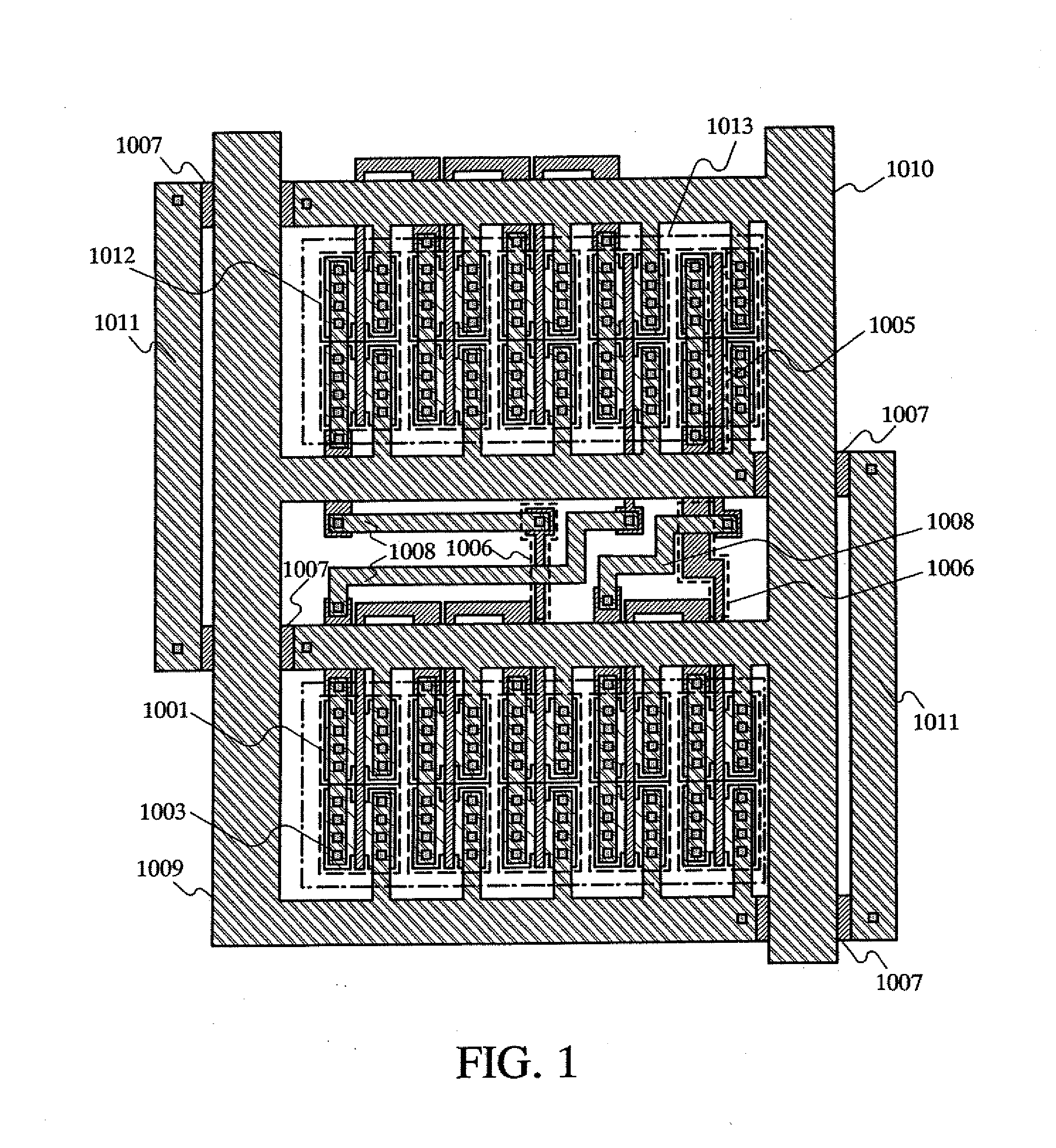
[0063]In this embodiment mode, a mask layout of a functional circuit in a semiconductor device and a display device according to the present invention is described. FIG. 1 shows a mask layout of this embodiment mode.
[0064]FIG. 1 shows an active layer 1001 which corresponds to a channel region, a source region, and a drain region of a TFT, a first wiring layer including a gate wiring 1005, a wiring 1006 between TFTs, and a first wiring 1007 which forms a power supply wiring or a ground wiring in a grid-like arrangement (hereinafter referred to as a first wiring for forming in a grid-like arrangement), a contact 1003 for connecting the first wiring and a second wiring or the active layer and the second wiring electrically, a second wiring layer including of a wiring 1008 between TFTs, a power supply wiring 1009, a ground wiring 1010, and the second wiring 1011 which forms a power supply wiring or a ground wiring in a grid-like arrangement (hereinafter referred to as a second wiring fo...
embodiment mode 2
[0071]In this embodiment mode, a mask layout of a functional circuit in a semiconductor device and a display device according to the present invention which is different from Embodiment Mode 1 is described. FIG. 3 shows a mask layout of this embodiment mode. It is to be noted that portions which are identical in FIG. 1 are denoted by the same reference symbols.
[0072]FIG. 3 shows the active layer 1001 which corresponds to a channel region, a source region, and a drain region of a TFT, the first wiring layer including the gate wiring 1005, the wiring 1006 between TFTs, and the first wiring 1007 which forms a power supply wiring or a ground wiring in a grid-like arrangement (hereinafter referred to as a first wiring for forming in a grid-like arrangement), the contact 1003 for connecting the first wiring and a second wiring or the active layer and the second wiring electrically, the second wiring layer including the wiring 1008 between TFTs, the power supply wiring 1009, the ground wir...
embodiment
Embodiment 1
[0078]In this embodiment as an example of a display device of the invention, a display device in which a CPU, an SRAM and the like are formed over the same substrate is explained.
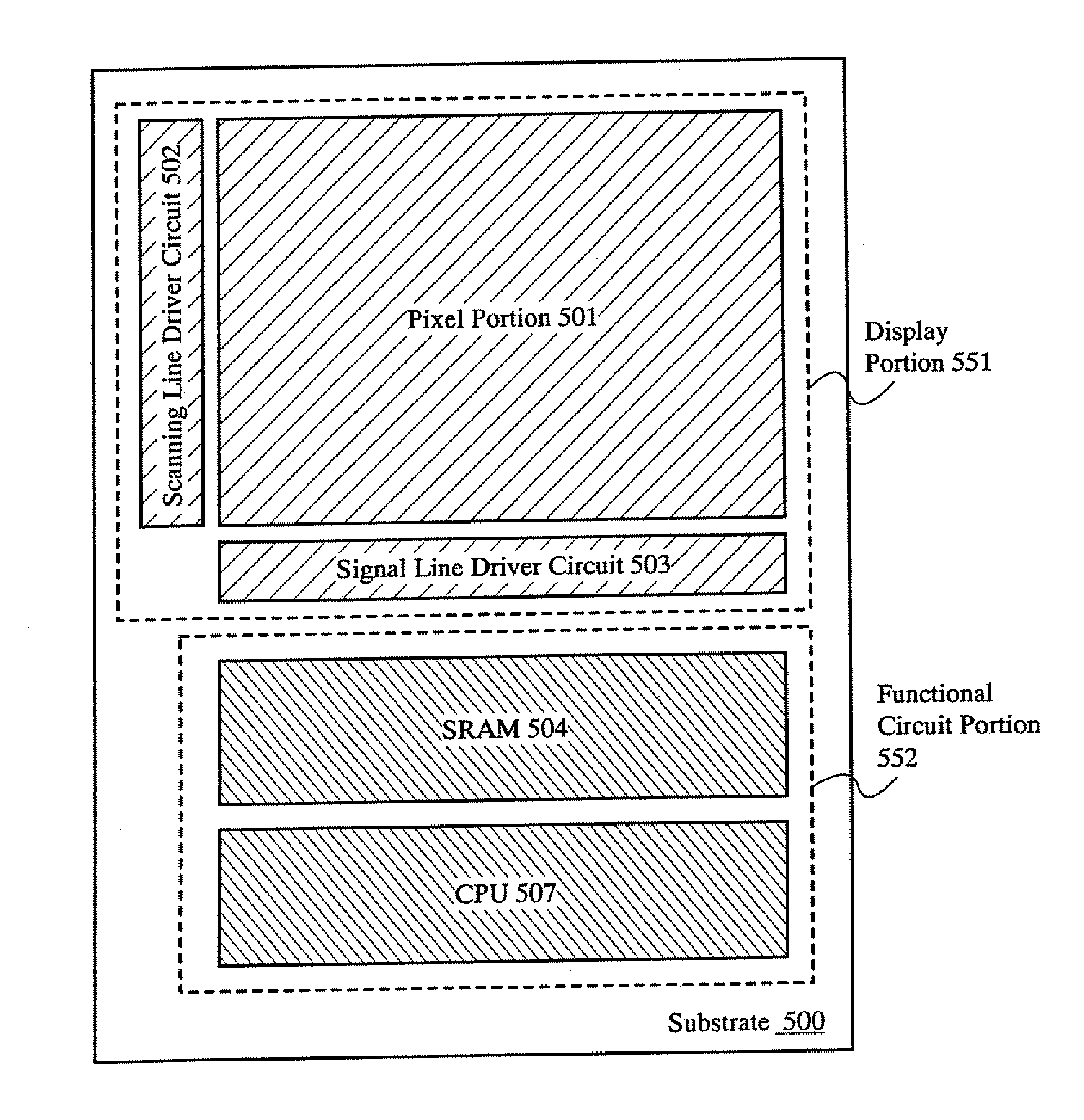
[0079]FIG. 4 shows a top view of a display device of the embodiment. The display device in FIG. 4 includes a display portion 551 and a functional circuit portion 552 which are formed by using TFTs formed over a substrate 500 having an insulating surface. The display portion 551 includes a pixel portion 501, a scanning line driver circuit 502, and a signal line driver circuit 503. Also, the functional circuit portion 552 includes a CPU 507 and an SRAM (memory circuit) 504. In the display portion 551, the pixel portion 501 displays an image. Further, the scanning line driver circuit 502 and the signal line driver circuit 503 control an input of a video signal to each pixel in the pixel portion 501. The SRAM 504 is formed by using a plurality of memory cells (not shown) arranged in matrix. One of t...
PUM
| Property | Measurement | Unit |
|---|---|---|
| thickness | aaaaa | aaaaa |
| thickness | aaaaa | aaaaa |
| thickness | aaaaa | aaaaa |
Abstract
Description
Claims
Application Information