Plasma processing system, antenna, and use of plasma processing system

a processing system and plasma technology, applied in the field of plasma processing system, can solve the problems of inability to accurately machine the metal cap and the protection cap, non-uniform and unstable plasma, and possible gaps between plasma and the other sid

Inactive Publication Date: 2008-12-11
TOKYO ELECTRON LTD +1
View PDF7 Cites 256 Cited by
  • Summary
  • Abstract
  • Description
  • Claims
  • Application Information

AI Technical Summary

Benefits of technology

[0006]According to this configuration, a portion of the exposed surface of the metal electrode is covered by a dielectric cover. This may reduce the electric field near the metal electrode, thereby increasing the plasma uniformity. When two or more surfaces are machined, a gap may occur therebetween because of poor machining accuracy. The gap may generate an abnormal discharge.
[0007]According to the configuration, however, a surface of the exposed portion of the metal electrode is covered by a dielectric cover. In this way, when only a surface of the exposed portion of the metal electrode, such as the bottom surface or the peripheral surface of the metal electrode, is covered by the dielectric cover, the metal electrode and the dielectric cover may be in close contact. This may eliminate the gap between the metal electrode and the dielectric cover, thereby reducing the abnormal discharge and generating a uniform and stable plasma. Because the highly accurate machining is unnecessary, the cost may be reduced.
[0010]The exposed surface of the metal electrode may therefore be formed to have no surface generally parallel to the target object to reduce the electric field near the metal electrode and increase the uniformity of the plasma.
[0015]Therefore, an electromagnetic wave at a frequency of 1 GHz or less, for example, may be used to excite a uniform and stable plasma from a single F-based gas. The single F-based gas may not be effective in exciting a uniform and stable plasma using a certain degree of power of an electromagnetic wave at a frequency of 2.45 GHz because the surface wave is not spread. Practical power of the electromagnetic wave may thus be used to excite a cleaning gas to generate a plasma. The plasma may clean the interior of the plasma processing system.

Problems solved by technology

When, unfortunately, the entire metal cap is covered by the protection cap and one surface of the metal cap such as the bottom surface or the peripheral surface is in close contact with the protection cap, a gap may exist on other surfaces of the metal cap, an abnormal discharge may be generated in the gap, and the discharge may make the plasma nonuniform and unstable.
In contrast, it is costly to accurately machine the metal cap and the protection cap to bring any surface of the metal cap into close contact with the protection cap to eliminate the gap.
When two or more surfaces are machined, a gap may occur therebetween because of poor machining accuracy.
The gap may generate an abnormal discharge.

Method used


Image

  • Plasma processing system, antenna, and use of plasma processing system
  • Plasma processing system, antenna, and use of plasma processing system
  • Plasma processing system, antenna, and use of plasma processing system

Examples


first embodiment

Modification of First Embodiment

[0098]Modifications 1 and 2 of the metal electrode 310 of the first embodiment will be described.

modification 1

[0099]The simulation results show that of the exposed portion of the metal electrode 310, the surface parallel to the substrate G induces the electric field concentration. It is thus preferable that the exposed portion of the metal electrode 310 has a shape that does not have a surface parallel to the substrate G. The modification includes, for example, a cone as shown in FIG. 8. The modification may also provide a hemisphere as shown in FIG. 9. The metal electrode 310 in FIGS. 8 and 9 has advantages including a lower cost due to no dielectric cover attached to the electrode 310 and less electric field concentration due to no surface parallel to the substrate G.

[0100]When the exposed portion of the metal electrode 310 has a cone shape as shown in FIG. 8, for example, six gas passages 310a may be provided at regular intervals to introduce the gas down from the gas passages 310a at 45 degrees with respect to the vertical direction. The end of the cone in FIG. 8 may be rounded to reduc...

modification 2

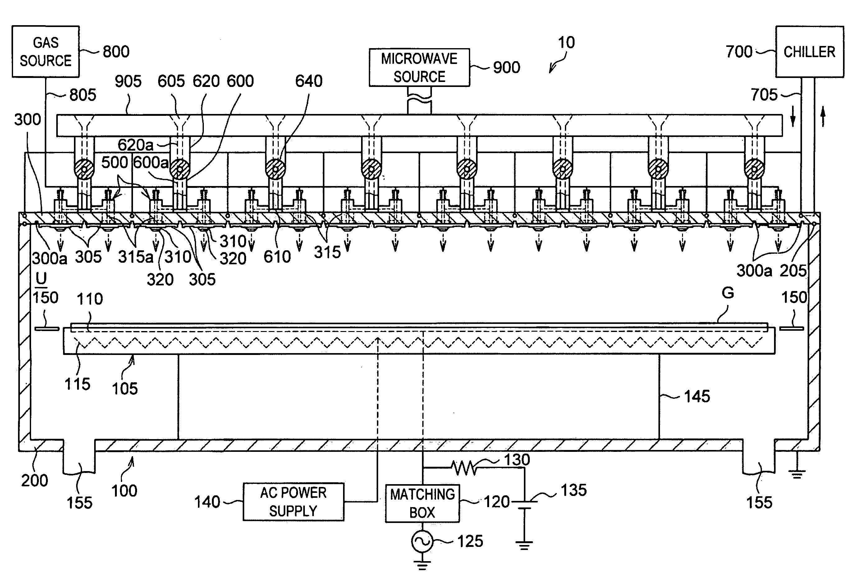
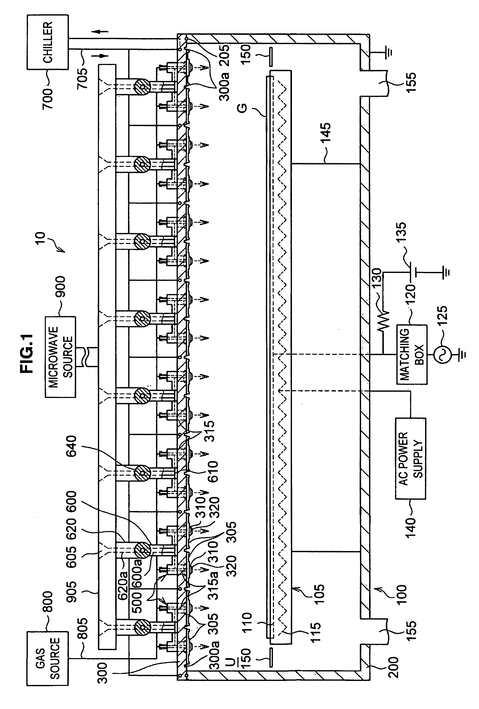
[0104]FIG. 12 shows the cross-sectional view taken along the line X-X in FIG. 11. FIG. 11 shows the cross-sectional view taken along the line Y-Y in FIG. 12. With reference to FIG. 11, the metal electrode 310 has a basal portion that extends into the through-hole 305a of the dielectric plate 305. Additionally, the inner conductor 315a of the coaxial waveguide 315 and the metal electrode 310 are screwed and coupled to each other using a male screw 315d at the end portion of the inner conductor 315a and using a female screw 310b at the basal portion of the metal electrode 310.

[0105]With reference to FIG. 6, which shows the dielectric ring 410 and the O-ring 415b, the O-ring 415b is first fitted in a space and then the dielectric ring 410 is attached. During attaching the dielectric ring 410, it may damage the O-ring 415b. In the structure in FIG. 11, the dielectric plate 305 tapers at the top. The dielectric plate 305 may thus be fitted more smoothly and the dielectric plate 305 may l...


PUM

PropertyMeasurementUnit
frequencyaaaaaaaaaa
heightaaaaaaaaaa
frequencyaaaaaaaaaa

Abstract

A plasma processing system 10 includes a processing chamber 100, a microwave source 900 that outputs a microwave, an inner conductor of a coaxial waveguide 315a that transfers the microwave, a through-hole 305a, a dielectric plate 305 that transmits the microwave transferred through the inner conductor 315a and discharges it into a processing chamber 100, and a metal electrode 310 that is coupled to the inner conductor 315a via the through-hole 305a, the metal electrode 310 being exposed on the surface of the dielectric plate 305 that faces the substrate with at least a portion of the metal electrode 310 being adjacent to the surface of the dielectric plate 305 that faces the substrate. A surface of the exposed surface of the metal electrode 310 is covered by the dielectric cover 320.

Description

CROSS-REFERENCE TO RELATED APPLICATION[0001]The present invention contains subject matter related to Japanese Patent Application JP 2007-153544, filed in the Japan Patent Office on Jun. 11, 2007 and Japanese Patent Application JP 2008-140382, filed in the Japan Patent Office on May 29, 2008, the entire contents of which being incorporated herein by reference.FIELD OF THE INVENTION[0002]The present invention relates to a plasma processing system that excites a gas using an electromagnetic wave and applies a plasma process to a target object, and more particularly, to a plasma processing system that includes an antenna for supplying a low-frequency electromagnetic wave into the processing chamber.BACKGROUND OF THE INVENTION[0003]Various methods have been developed to use a waveguide or an coaxial waveguide to introduce an electromagnetic wave into a plasma processing chamber. One of the methods uses a coaxial waveguide having a cylindrical center conductor therein and a dielectric dis...

Claims


Application Information

Patent Timeline
Patent Type & Authority Applications(United States)
IPC IPC(8): H01Q1/36C23C16/54C23C16/452B08B6/00
CPCB08B7/00B08B7/0035C23C16/45565C23C16/45572C23C16/45574C23C16/511H01J37/32192H01J37/3222H01J37/32229
Inventor HIRAYAMA, MASAKIOHMI, TADAHIRO
Owner TOKYO ELECTRON LTD
Why Eureka
Try Eureka