Method for Production of a Laminate Polishing Pad

a technology of polishing pad and laminate, which is applied in the direction of grinding machine, grinding device, manufacturing tool, etc., can solve the problems of cushioning performance, large number of production steps, and low productivity rate, and achieve excellent productivity rate, reduce production steps, and prevent the effect of groove clogging

Active Publication Date: 2008-12-11
ROHM & HAAS ELECTRONICS MATERIALS CMP HLDG INC
View PDF72 Cites 35 Cited by
  • Summary
  • Abstract
  • Description
  • Claims
  • Application Information

AI Technical Summary

Benefits of technology

[0019]It is an object of the invention to provide a method for production of a laminate polishing pad which includes a reduced number of production steps and is excellent in productivity rate. It is another object of the invention to provide a method for production of a laminate polishing pad which causes no detachment between a polishing layer and a cushion layer and can prevent the groove clogging caused by a slurry or the like and to provide a laminate polishing pad produced by such a method. It is a further object of the invention to provide a method for production of a semiconductor device with such a laminate polishing pad.

Problems solved by technology

Laminate polishing pads are produced by laminating, with an adhesive or double-side tape, a plurality of resin sheets, such as a polishing layer and a cushion layer, obtained by the method described above, and such a method for production of laminate polishing pads has the problems of a large number of production steps and low productivity rate.
Polyurethane foam sheets are excellent in locally planarizing performance but have insufficient cushion performance, and therefore it is difficult to evenly apply a pressure to the entire surface of a wafer from such a polyurethane foam sheet.
However, the conventional laminate polishing pads have a problem in which since they are produced by bonding the polishing layer to the cushion layer with a double-side tape (a pressure-sensitive adhesive layer), a slurry can intrude between the polishing layer and the cushion layer during polishing to reduce the adhesion of the double-side tape so that the polishing layer can be detached from the cushion layer.
When the surface of such laminate polishing pads are provided with grooves, there is also a problem in which abrasive grains in a slurry, polishing dust and the like tend to stay in the grooves to cause groove clogging so that the polishing speed can be reduced or made unstable and the planarity or in-plane uniformity of the polished substance can be reduced.

Method used


Image

  • Method for Production of a Laminate Polishing Pad
  • Method for Production of a Laminate Polishing Pad
  • Method for Production of a Laminate Polishing Pad

Examples


example 1

[0117]A mixture of 32 parts by weight of toluene diisocyanate (a mixture of 2,4-diisocyanate / 2,6-diisocyanate=80 / 20), 8 parts by weight of 4,4′-dicyclohexylmethane diisocyanate, 54 parts by weight of polytetramethylene glycol (1006 in number average molecular weight), and 6 parts by weight of diethylene glycol was prepared and stirred and heated at 80° C. for 120 minutes so that an isocyanate-terminated prepolymer (2.1 meq / g in isocyanate equivalent) was prepared. One hundred parts by weight of the isocyanate-terminated prepolymer and 3 parts by weight of a silicone surfactant (SH-192 manufactured by Dow Corning Toray Co., Ltd.) were mixed and controlled to have a temperature 80° C. so that a mixture A was prepared. In a mixing chamber, 80 parts by weight of the mixture A and 20 parts by weigh of 4,4′-methylenebis(o-chloroaniline) (Iharacuamine MT manufactured by Ihara Chemical Industry Co., Ltd.) melted at 120° C. were mixed. At the same time, air was mixed into the resulting mixtu...

example 2

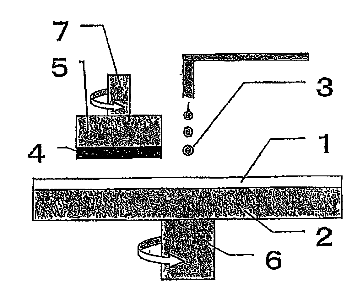
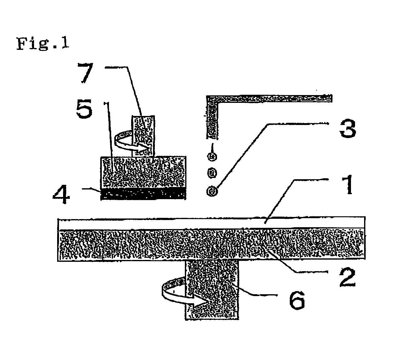
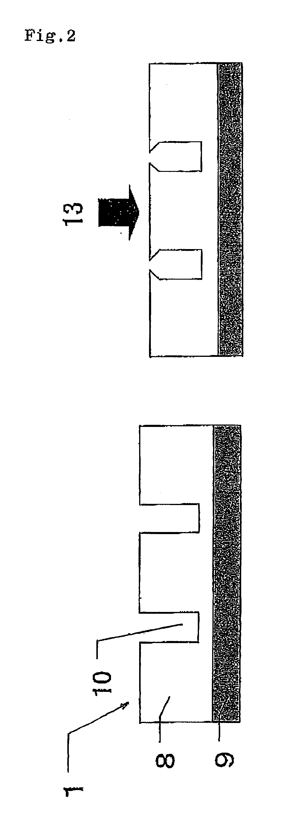
[0119]While a cushion layer made of a polyethylene foam (Toraypef manufactured by Toray Industries, Inc.) with its surface buffed and its thickness controlled to 1.7 mm was fed, a projection and recess-forming roll being heated at 90° C. and rotated was pressed against the cushion layer surface so that projections (H: 0.13 mm, W: 8 mm) were formed at regular intervals on the surface of the cushion layer. The cell-dispersed urethane composition prepared in Example 1 was continuously ejected onto the surface of the cushion layer. Laminate polishing sheets were then prepared using the process of Example 1. The polishing layer surface of each resulting laminate polishing sheet was grooved using a grooving machine (manufactured by Toho Koki Co., Ltd.) such that each groove was located between the adjacent projections of the cushion layer surface, so that a laminate polishing pad (h: 1.3 mm, w1: 2 mm, w2: 12 mm) was produced.


PUM

PropertyMeasurementUnit
heightaaaaaaaaaa
widthaaaaaaaaaa
particle sizeaaaaaaaaaa

Abstract

Disclosed is a method for production of a laminate polishing pad which comprises a reduced number of steps and is excellent in productivity rate, and which causes no detachment between a polishing layer and a cushion layer and can prevent the groove clogging caused by a slurry or the like. Also disclosed is a laminate polishing pad produced by the method. A method for production of a laminate polishing pad, comprising the steps of: preparing a cell-dispersed urethane composition by a mechanical frothing process; ejecting the cell-dispersed urethane composition onto a cushion layer continuously while feeding the cushion layer; curing the cell-dispersed urethane composition while controlling the thickness of the composition evenly to form a polishing layer made of a polyurethane foam, thereby producing a long laminate sheet; and cutting the long laminate sheet.

Description

TECHNICAL FIELD[0001]The present invention relates to a method for production of a laminate polishing pad by which the planarizing processing of optical materials such as lenses, reflecting mirrors and the like, silicon wafers, glass substrates for hard disks, aluminum substrates, and materials requiring a high degree of surface planarity such as those in general metal polishing processing can be carried out stably with high polishing efficiency. The laminate polishing pad obtained by the manufacturing method of the present invention is used particularly preferably in a process of planarizing a silicone wafer, and a device having an oxide layer, a metal layer or the like formed on a silicon wafer, before lamination and formation of the oxide layer, the metal layer or the like.BACKGROUND ART[0002]Production of a semiconductor device involves a step of forming an electroconductive film on the surface of a wafer to form a wiring layer by photolithography, etching etc., a step of formin...

Claims


Application Information

Patent Timeline
Patent Type & Authority Applications(United States)
IPC IPC(8): B24B1/00B24D11/00B24B37/20B24B37/24H01L21/304
CPCB24B37/20B24D18/00B29C44/32C08G18/12C08G18/4854C08G18/724C08G18/758C08G18/7621C08G2101/0025C08G18/3814B29C44/326B29C44/321B29C44/332C08G2110/0025
Inventor HIROSE, JUNJIDOURA, MASATO
Owner ROHM & HAAS ELECTRONICS MATERIALS CMP HLDG INC
Why Eureka
Try Eureka