Motor Control Device
a technology of motor control and control device, which is applied in the direction of motor/generator/converter stopper, dynamo-electric gear control, and dynamo-electric converter control. it can solve the problems of low accuracy, low workability, and degradation of torque control accuracy or a reduction in the maximum torque. achieve the effect of improving workability and improving accuracy
- Summary
- Abstract
- Description
- Claims
- Application Information
AI Technical Summary
Benefits of technology
Problems solved by technology
Method used
Image
Examples
first embodiment
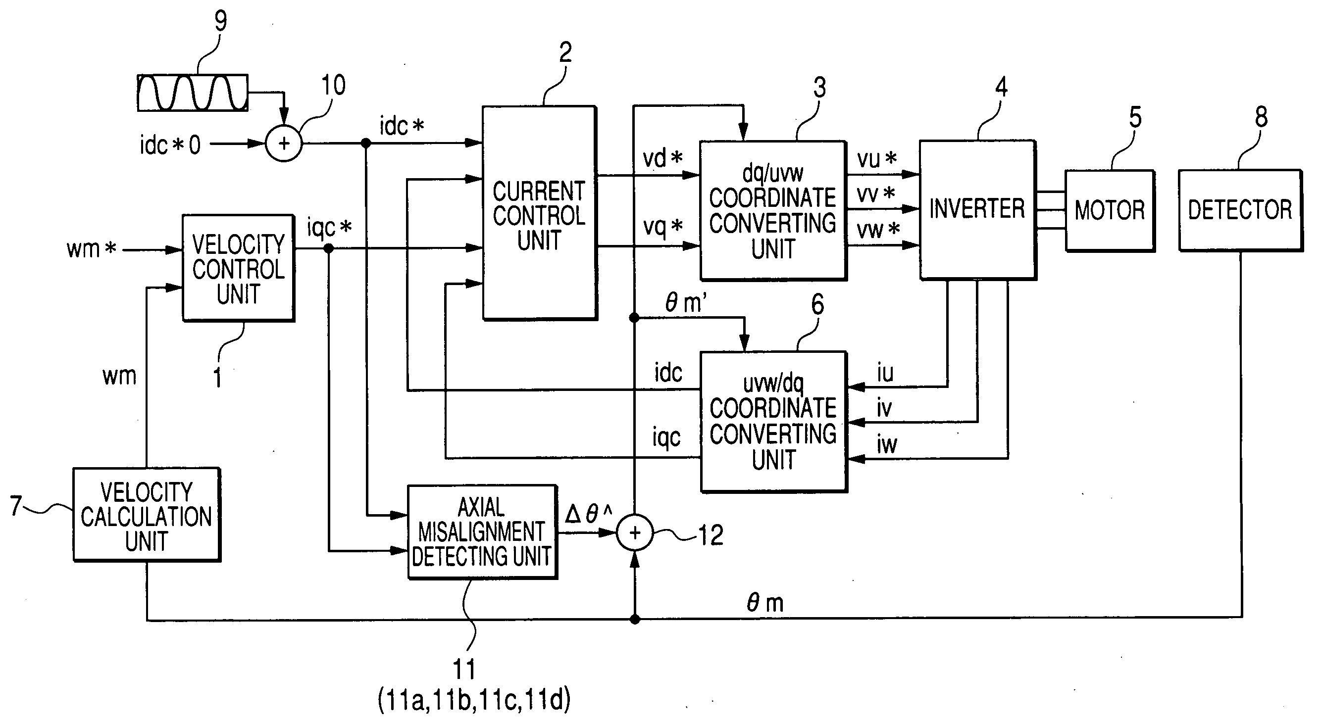
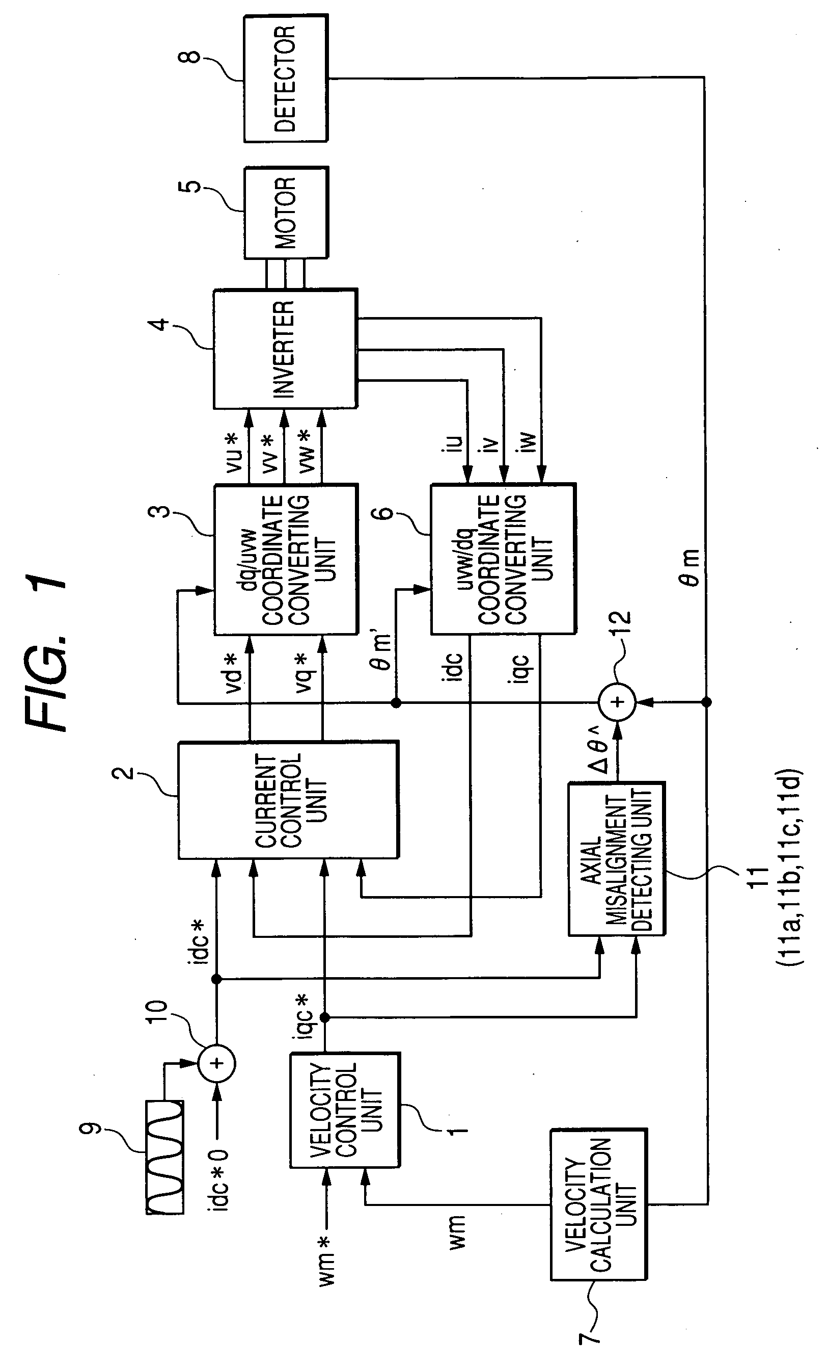
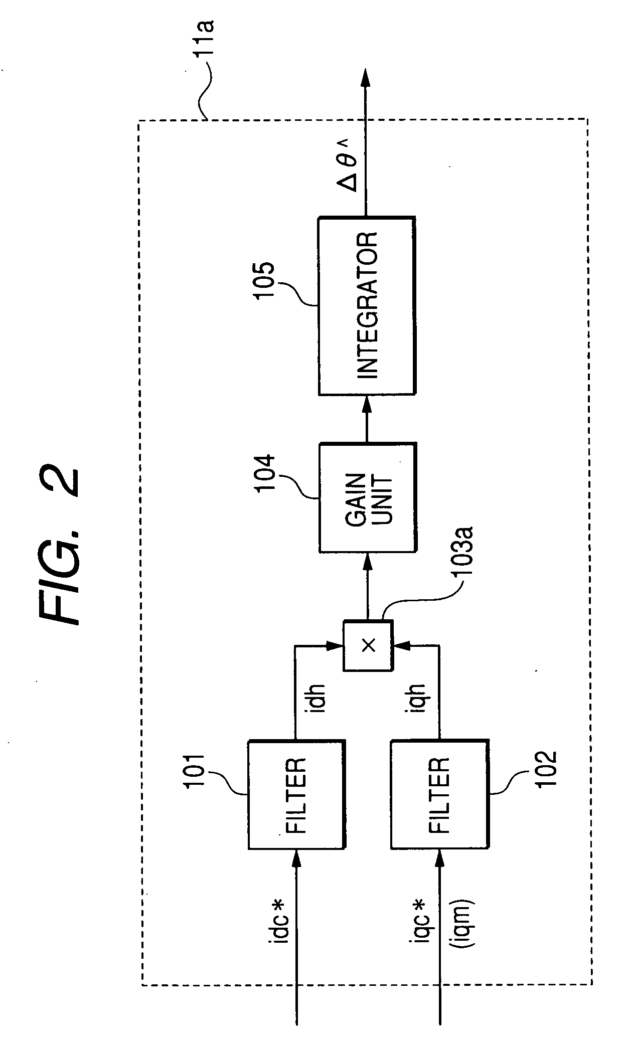
[0041]FIG. 1 is a block diagram showing the configuration of a motor control device according to a first embodiment of the invention. FIG. 2 is a block diagram showing an example of the configuration of an axial misalignment detecting unit 11a in the motor control device according to the first embodiment of the invention. FIG. 3 is a diagram illustrating the relationship between a dq-axis (dm-qm axis) of an actual motor and a dq-axis (dc-qc axis) for control.
[0042]The processing operation of the motor control device according to the first embodiment will be described below with reference to FIGS. 1 to 3.
[0043]In FIG. 1, a velocity control unit 1 receives a velocity command wm* and an actual velocity wm, performs current control to cause the actual velocity wm to follow the velocity command wm* using PI control or the like, and outputs a q-axis current command iqc*. Further, a current control unit 2 receives a d-axis current command idc*, the q-axis current command iqc*, a d-axis cur...
second embodiment
[0072]The processing operation of the axial misalignment detecting unit 11b in the motor control device according to the second embodiment will be described with reference to FIG. 4. In FIG. 4, reference numerals 101, 102, 104, and 105 are the same as those of FIG. 2 and the descriptions thereof will be omitted for simplicity. The axial misalignment detecting unit 11b shown in FIG. 4 further includes a sign detector 106 serving as a first sign detector and a sign detector 107 serving as a second sign detector. The sign detector 106 and the sign detector 107 are interposed between the input filters 101, 102 and the adaptive input calculation unit 103a in the axial misalignment detecting unit 11a shown in FIG. 2.
[0073]The sign detectors 106, 107 receive a d-axis signal for axial misalignment detection idh and a q-axis signal for axial misalignment detection iqh, respectively, which are extracted through the input filters 101, 102, respectively, detect signs of the d-axis signal for ax...
third embodiment
[0078]The processing operation of the axial misalignment detecting unit 11c in the motor control device according to the third embodiment will be described with reference to FIG. 5.
[0079]The input filters 101, 102 perform extracting processes on the d-axis current command idc* and the q-axis current command iqc* (or torque current error iqm), respectively, which are input to the axial misalignment detecting unit 11c, and output the d-axis signal for axial misalignment detection idh and the q-axis signal for axial misalignment detection iqh.
[0080]An estimation output calculation unit 108 multiplies the d-axis signal for axial misalignment detection idh that is extracted by the input filter 101 and an axial misalignment angle measurement value Δθ̂ to be described later, and outputs an estimation output (idh×Δθ̂). Further, an axial misalignment error calculation unit 109 outputs axial misalignment error based on a difference between the q-axis signal for axial misalignment detection iq...
PUM
 Abstract
Description
Claims
Application Information
 - R&D
- Intellectual Property
- Life Sciences
- Materials
- Tech Scout
- Unparalleled Data Quality
- Higher Quality Content
- 60% Fewer Hallucinations
Browse by: Latest US Patents, China's latest patents, Technical Efficacy Thesaurus, Application Domain, Technology Topic, Popular Technical Reports.
© 2025 PatSnap. All rights reserved.Legal|Privacy policy|Modern Slavery Act Transparency Statement|Sitemap|About US| Contact US: help@patsnap.com


