
Metalized Film Capacitor, Case Mold Type Capacitor Using the Same, Inverter Circuit, and Vehicle Drive Motor Drive Circuit

a metal sprayed electrode and film technology, applied in the direction of wound capacitors, fixed capacitors, fixed capacitor details, etc., can solve the problems of reducing reliability, increasing cost, and affecting the efficiency of metal sprayed electrodes, so as to improve volumetric efficiency, reduce cost, and reduce the effect of spherical thickness

Active Publication Date: 2008-12-18
PANASONIC CORP
View PDF10 Cites 23 Cited by
  • Summary
  • Abstract
  • Description
  • Claims
  • Application Information

AI Technical Summary

Benefits of technology

[0018]The present invention provides a metalized film capacitor that achieves a large capacity and a small and thin size, improves volumetric efficiency, and has an excellent productivity and reliability. Furthermore, the present invention provides a metalized film capacitor capable of exhibiting a stable performance in a wide temperature range, a case mold type capacitor using the same, an inverter circuit and a vehicle drive motor drive circuit.
[0020]In the metalized film capacitor in accordance with the present invention, by increasing the dimension in which the pair of metalized films is shifted in the width direction, a bonding state between the metal vapor-deposited electrode and electrodes formed on the end surface thereof is maintained stable. Therefore, even if the use temperature range is widened and the thermal stress is increased, a stable contact state between the metal sprayed electrode and the film can be maintained. The deterioration of tan δ can be suppressed and excellent electric performance can be maintained.
[0022]As mentioned above, in the metalized film capacitor in accordance with the present invention, even when the flattening ratio of the capacitor element having an elliptical sectional shape is increased and a large capacity is achieved, it is possible to set the strength of the winding core to be an suitable value. Therefore, it is possible to obtain an effect of realizing a metalized film capacitor that achieves a large capacity and a small and thin size, improves volumetric efficiency, and has an excellent productivity and reliability.

Problems solved by technology

However, when the number of elements is increased, there are problems that cost rises and reliability is reduced.
Consequently, a portion in which the metal sprayed electrode and the film are brought into contact with each other is the most susceptible to thermal stress.
As a result, the state in which the metal sprayed electrode and the film are brought into contact with each other is further deteriorated.
Due to this deterioration, electrical loss (tan δ) that is one of the electrical characteristics of a capacitor may be deteriorated.
However, it is not easy to produce a large laminated capacitor by laminating thin films and cutting them.
Furthermore, there is a problem as to withstand voltage and it is known that the intended withstand voltage per unit thickness cannot be achieved.
When the thickness of materials of the winding core is thick and the strength is too strong, it is difficult to pull out a holding jig (not shown).
Furthermore, as shown in FIG. 16, in addition to the difficulty in flattening, there arises a problem that winding core 400C is returned to the original state after flattening, so that the capacitor element is swollen in the direction of 400D.
Thus, the capacitor element that has been processed in a flat shape becomes weak in strength and a desired shape cannot be maintained.

Method used


Image

  • Metalized Film Capacitor, Case Mold Type Capacitor Using the Same, Inverter Circuit, and Vehicle Drive Motor Drive Circuit
  • Metalized Film Capacitor, Case Mold Type Capacitor Using the Same, Inverter Circuit, and Vehicle Drive Motor Drive Circuit
  • Metalized Film Capacitor, Case Mold Type Capacitor Using the Same, Inverter Circuit, and Vehicle Drive Motor Drive Circuit

Examples


first exemplary embodiment

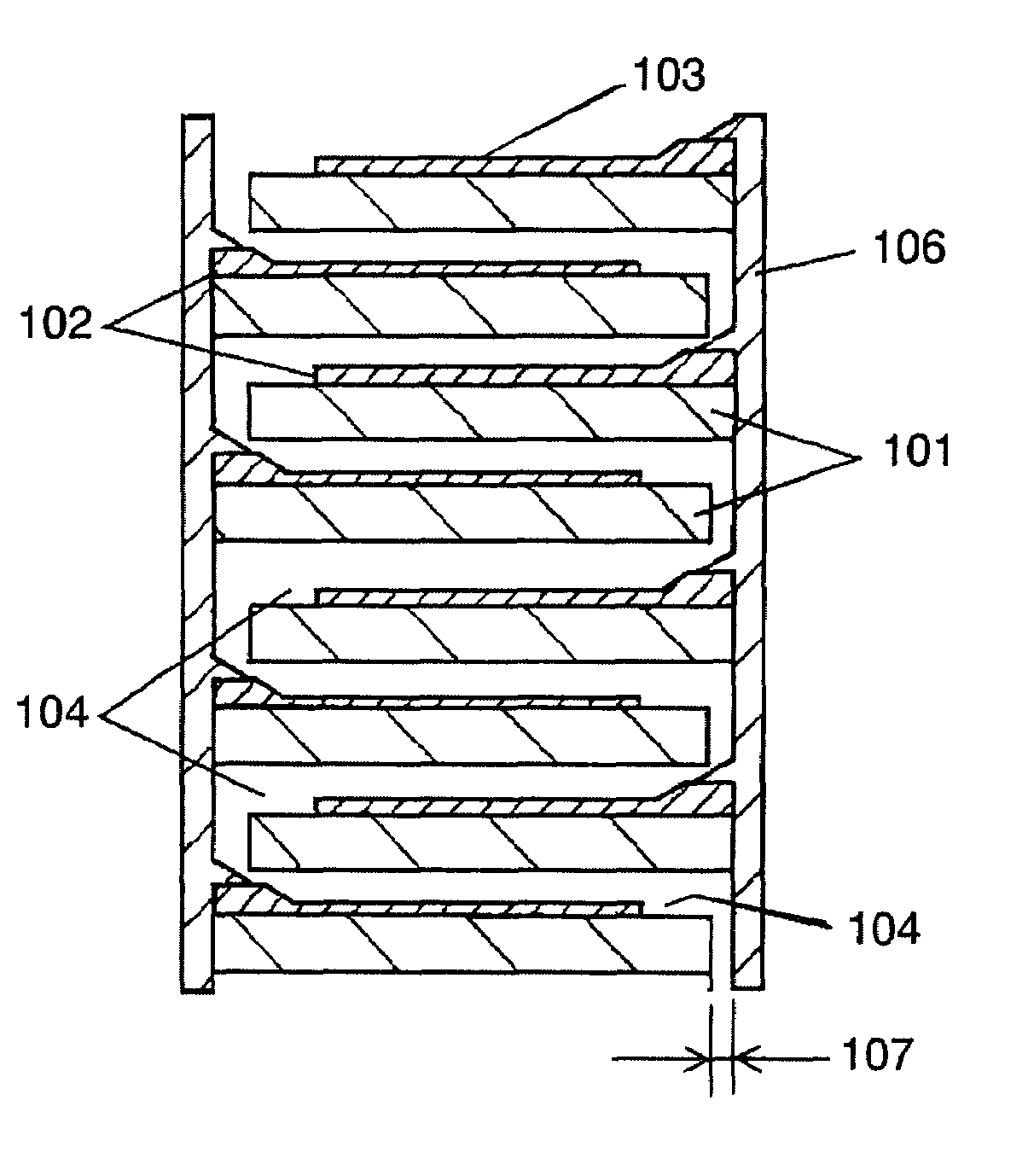
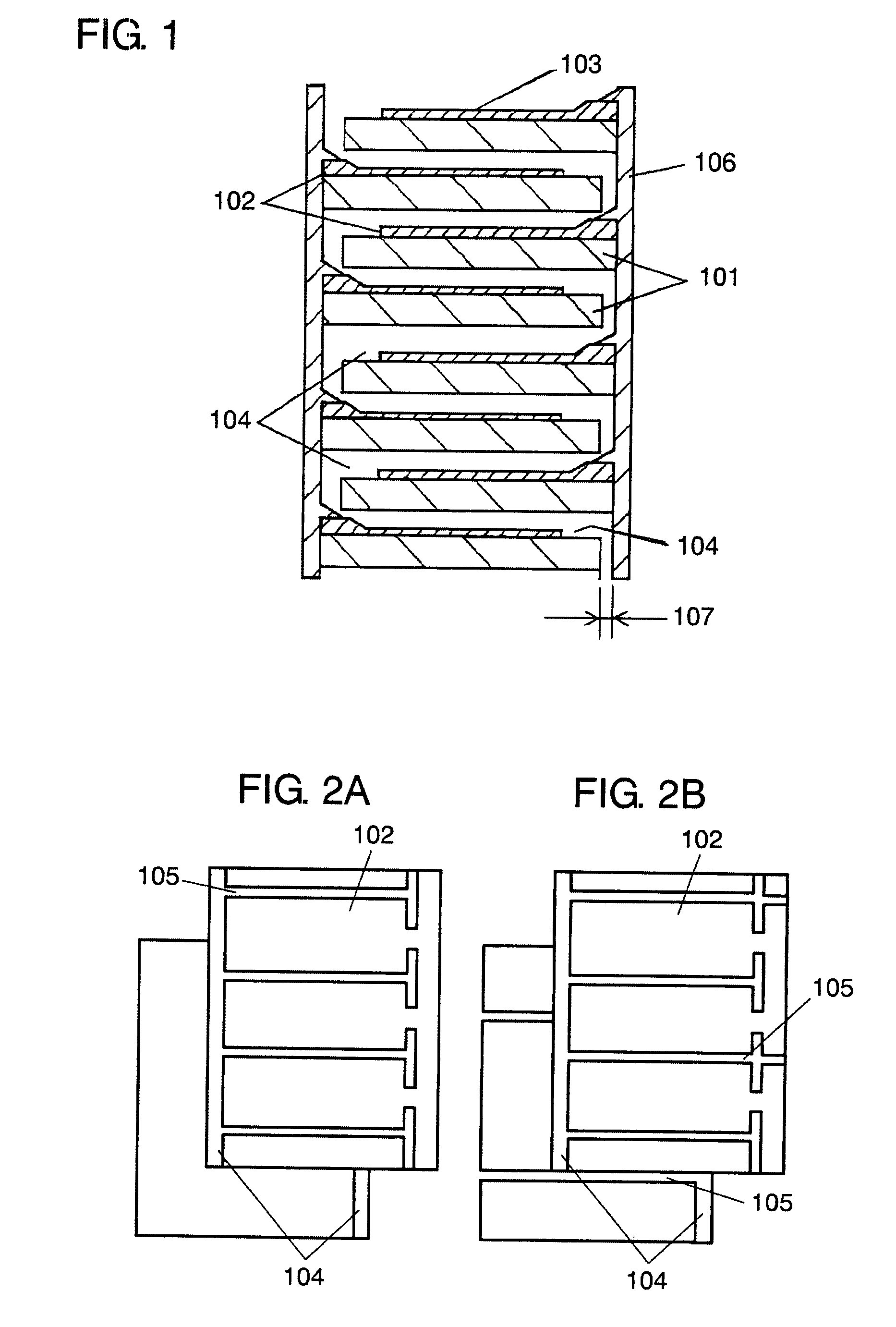
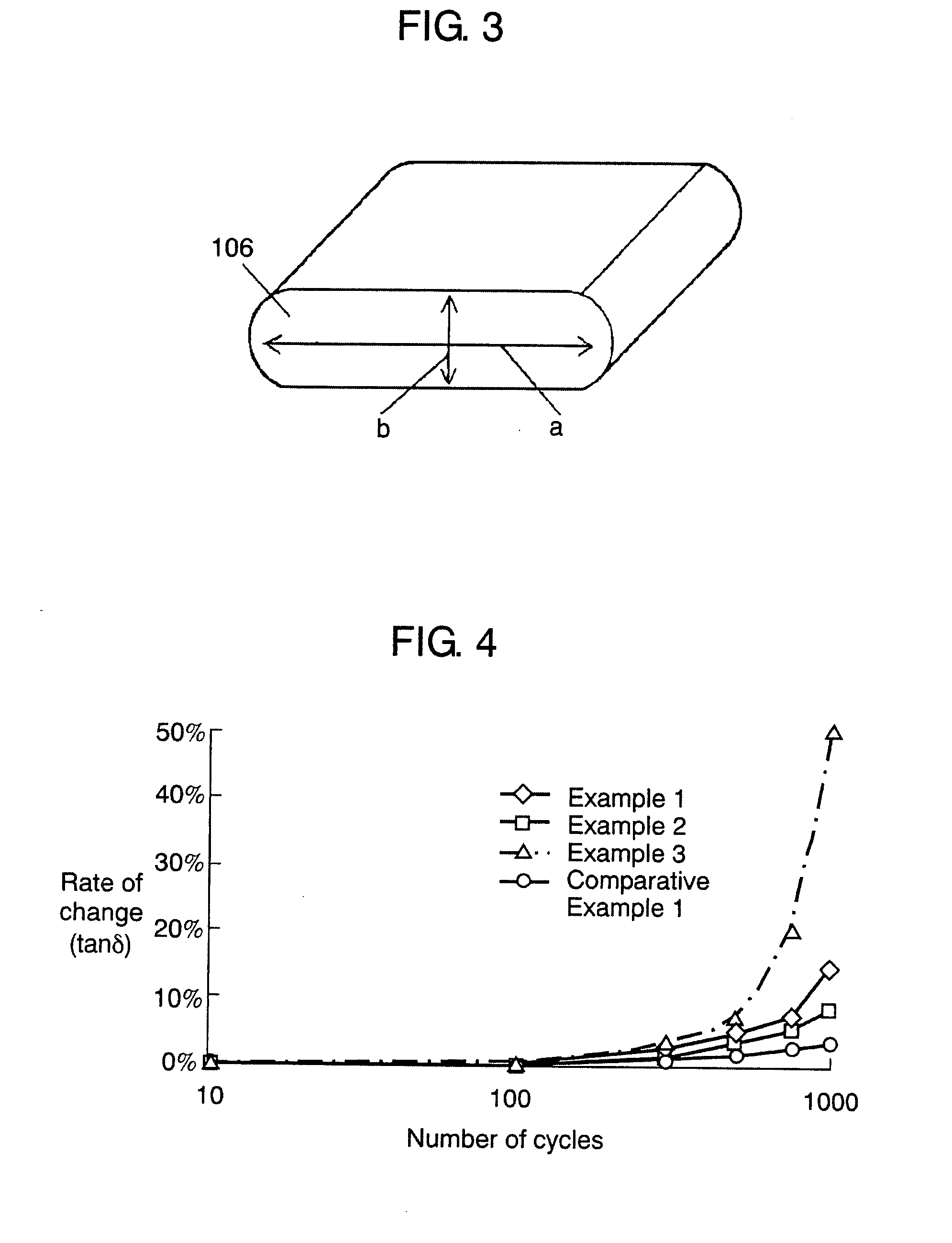
[0070]FIG. 1 is a sectional view showing a configuration of a metalized film capacitor in accordance with a first exemplary embodiment of the present invention; FIGS. 2A and 2B are plan views showing a metalized film used in the metalized film capacitor; and FIG. 3 is a perspective view showing a structure of the metalized film capacitor.

[0071]In FIGS. 1 to 3, on the surface of dielectric film 101 made of one of organic polymer materials, for example, polypropylene, metal vapor-deposited electrode 102 is formed by, for example, vacuum metallizing. Thus, metalized film 103 is formed. On the surface of dielectric film 101, margin 104 in which metal vapor-deposited electrode 102 is not formed is provided. Margin 104 is continuously formed at the side of one end of dielectric film 101 in the longitudinal direction. Furthermore, slit 105 is provided in which metal vapor-deposited electrode 102 is not formed so as to expose dielectric film 101. Slits 105 are formed at appropriately equal ...

example 9

[0086]Example 9 is carried out the same as in Example 8 except that a type in which a metal vapor-deposited electrode is divided in the width of 15 mm by slit 105 shown in FIG. 2B is used as metalized film 103.

example 10

[0087]Example 10 is carried out the same as in Example 8 except that offset 107 that is a shift amount of metalized film 103 is set to 1.3 mm.


PUM


Abstract

A metalized film capacitor capable of exhibiting stable performance in a wide temperature range is provided. The metalized film capacitor has an elliptical cross sectional shape having a major axis of 60 mm or above. In this capacitor, offset for shifting in the width direction of a pair of metalized film is set to 1.2 mm or above. Since the bonding state between metal vapor-deposited electrode and metal sprayed electrode formed on the end surface is stable, a stable contact between metal sprayed electrode and dielectric film is maintained, thereby preferably maintaining tan σ and exhibiting excellent performance even if the use temperature range is increased and the thermal stress is increased.

Description

[0001]The present invention relates to a metalized film capacitor used in various electrical equipments, industrial application, electric power, and the like, and particularly suitable for vehicle-mounted applications, a case mold type capacitor using the same, and an inverter circuit and a vehicle drive motor drive circuit.BACKGROUND ART[0002]Recently, in a car industry, environmental friendly technologies have been developed actively. For example, hybrid electric vehicles run by an electric motor and an engine (hereinafter, referred to as “HEV”) have been introduced in a market. An electric motor system for HEV has a high working voltage region such as several hundreds volts. Therefore, as capacitors used for such electric motor systems, metalized film capacitors having a high withstand voltage and excellent electric characteristics have been used.[0003]FIG. 14A is a developed perspective view showing a configuration of a conventional metalized film capacitor of this kind; and FIG...

Claims


Application Information

Patent Timeline
IPC IPC(8): H01G4/32
CPCH01G4/01H01G4/232H01G4/30H01G4/18H01G4/32H01G4/145Y02T10/7022H01G4/015Y02T10/70
Inventor TAKEOKA, HIROKISAITO, TOSHIHARUMIURA, TOSHIHISAIMAMURA, TAKESHINAGATA, YOSHINARI
Owner PANASONIC CORP
Learn More