Microphone package adapted to semiconductor device and manufacturing method therefor

a technology of semiconductor devices and microphones, applied in the direction of piezoelectric/electrostrictive transducers, electrostatic transducers of semiconductor, transducer types, etc., can solve the problems of inability to reliably protect the transducer from being exposed to excessive pressure variations, the manufacturing cost of the semiconductor device may be unexpectedly varied, etc., to achieve the effect of reducing the number of parts, reducing the manufacturing cost of the semiconductor device, and improving the manufacturing efficiency of the semiconductor devi

Inactive Publication Date: 2008-12-18
YAMAHA CORP
View PDF0 Cites 53 Cited by
  • Summary
  • Abstract
  • Description
  • Claims
  • Application Information

AI Technical Summary

Benefits of technology

[0030]In the above, the projected portion is not necessarily formed using an independent member independently of the housing; hence, it is possible to reduce the manufacturing cost of the semiconductor device by reducing the number of parts forming the housing. Since a part of the cover is simply bent to simultaneously form the sound hole and the projected portion, it is possible to improve the manufacturing efficiency of the semiconductor device.
[0031]It is possible to form a pipe having a plurality of small holes inside of the cavity of the housing, wherein a part of pressure variations entering into the pipe via the sound hole may be introduced into the cavity via the small holes, while the remaining of pressure variations is discharged towards the external space via a through-hole. Herein, pressure variations, which may reach the sound detector via the cavity, are subjected to diffraction and damping due to the small holes of the pipe. This makes it possible to prevent excessive pressure variations from being directly introduced into the cavity; hence, it is possible to prevent excessive stress from b

Problems solved by technology

In particular, when liquid droplets or dusts are attached to the transducer or when light is incident on the transducer, characteristics of the semiconductor sensor chip may be unexpectedly varied.
When excessive pressure variations are directly applied to the transducer via the sound hole of the housing, the transducer may be exposed to excessive stress.
Patent Document 1 teaches an

Method used


Image

  • Microphone package adapted to semiconductor device and manufacturing method therefor
  • Microphone package adapted to semiconductor device and manufacturing method therefor
  • Microphone package adapted to semiconductor device and manufacturing method therefor

Examples


first embodiment

1. First Embodiment

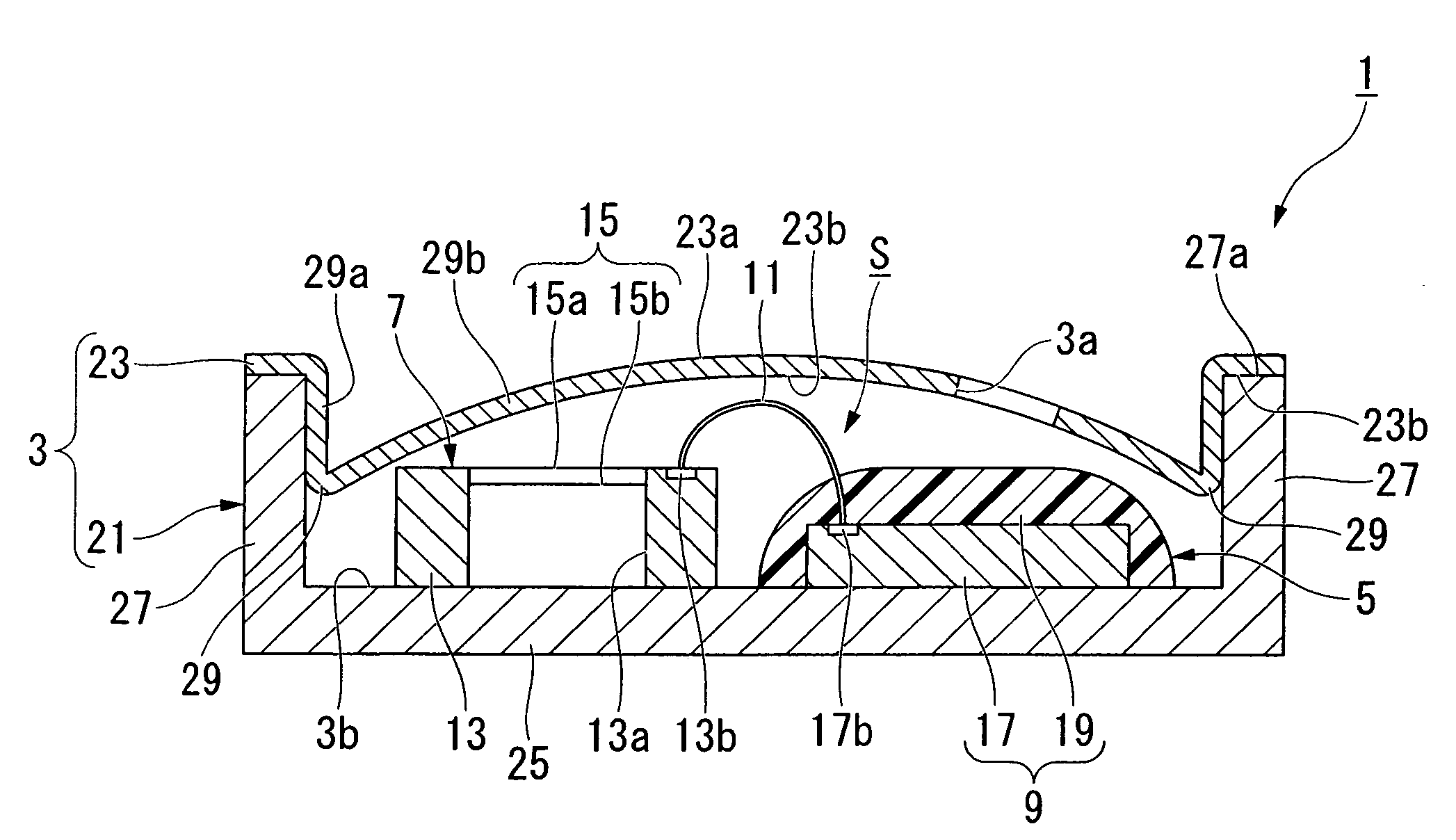
[0063]A first embodiment of the semiconductor device will be described with reference to FIG. 1 by way of a microphone package 1. The microphone package 1 includes a sound detection unit 5, which is encapsulated in a housing 3 having a hollow cavity S and a sound hole 3a communicating with the external space.

[0064]In the sound detection unit 5, a microphone chip 7 and a control circuit 9, both mounted on a mount surface 3b of the housing 3, are electrically connected together via a wire 11.

[0065]The microphone chip 7 is constituted of a support 13 (having an inner hole 13a running through in the thickness direction) and a sound detector 15, which is arranged to cover the inner hole 13a so as to detect variations of pressures such as sound pressures.

[0066]An electrode pad 13b joining a first end of the wire 11 is formed at a prescribed position of the support 13. The sound detector 15 is constituted of a fixed electrode 15a having a rectangular plate shape for cove...

second embodiment

2. Second Embodiment

[0106]Next, a semiconductor device 100 according to a second embodiment of the present invention will be described with reference to FIGS. 5 and 6. In the semiconductor device 100, a microphone chip (or a semiconductor sensor chip) 105 and an LSI chip 107 are formed on the mount surface of a substrate 3 having a box-like shape while a cover 109 is attached to an upper end 103a of the substrate 103, thus forming a microphone package.

[0107]The microphone chip 105 is constituted of a support 111 having an inner hole 111a running through in its thickness direction and a sound detector 113, which is arranged to cover the inner hole 111a of the support 111. The sound detector 113 detects variations of pressures such as sound pressures by way of vibrations thereof. The sound detector 113 is constituted of a fixed electrode 113a having a rectangular shape for covering the inner hole 111a of the support 111 and a diaphragm 113b, which is arranged opposite to the fixed ele...

third embodiment

3. Third Embodiment

[0145]Next, a semiconductor device 170 according to a third embodiment of the present invention will be described with reference to FIGS. 16 and 17, wherein parts identical to those of the foregoing semiconductor device 100 of the second embodiment are designated by the same reference numerals; hence, the detailed descriptions thereof will be omitted.

[0146]As shown in FIGS. 16 and 17, a sound hole 171 is formed at a prescribed position of the cover 109 so as to make the cavity S communicate with the external space of the semiconductor device 170. The sound hole 171 is constituted of a first recess 171a, which is carved from the surface 109a to the backside 109b of the cover 109, and a second recess 171b, which is carved from the backside 109b to the surface 109a of the cover 109. These recesses 171a and 171b are positioned just above the LSI chip 107 sealed with the resin seal 119. The first recess 171a and the second recess 171b are mutually deviated from each ot...


PUM


Abstract

A microphone package includes a sound detection unit, which further includes a microphone chip for detecting sound and a control circuit for controlling the microphone chip, a substrate having a mount surface for mounting the microphone chip and the control circuit and a ring-shaped side wall, which projects upwardly from the mount surface so as to surround the sound detection unit, and a cover that is arranged above the substrate so as to form a hollow cavity with the mount surface and the ring-shaped side wall of the substrate. A sound hole establishing communication between the cavity and the external space is formed in a prescribed position of the substrate or the cover, wherein a recess or a projection is formed inside of the cover. A directional regulator is formed in the housing so as to block excessive pressure variations and environmental factors from being directed to the microphone chip.

Description

BACKGROUND OF THE INVENTION[0001]1. Field of the Invention[0002]The present invention relates to microphone packages encapsulating microphone chips and semiconductor devices. The present invention also relates to semiconductor devices such as microphone chips and pressure sensor chips as well as manufacturing methods therefor.[0003]The present application claims priority on Japanese Patent Application No. 2007-157673 and Japanese Patent Application No. 2007-216990, the contents of which are incorporated herein by reference.[0004]2. Description of the Related Art[0005]Conventionally, various types of silicon condenser microphones, in which semiconductor sensor chips (e.g. microphone chips) having transducers for detecting variations of pressures such as sound pressures are arranged inside of housings having sound holes, have been developed and disclosed in various documents such as Patent Document 1.[0006]Patent Document 1: Japanese Patent Application Publication No. 2004-537182[0007...

Claims


Application Information

Patent Timeline
IPC IPC(8): H04R1/00H01L29/84
CPCH04R1/021H04R19/016H04R19/005H04R31/006
Inventor SHIRASAKA, KENICHIHIRADE, SEIJIMITSUOKA, KUNIHIKO
Owner YAMAHA CORP
Why Eureka
Try Eureka