Method for Determining Current Oxygen Loading of a 3-Way Catalytic Converter of a Lambda-Controlled Internal Combustion Engine

a technology of lambda-controlled internal combustion engine and catalytic converter, which is applied in the direction of electrical control, exhaust treatment electric control, instruments, etc., can solve the problems of not being able to compensate a fluctuation in the fuel/air ratio, and no information is available between said two limiting values about the actual, current oxygen loading of the catalytic converter

a technology of lambda-controlled internal combustion engine and catalytic converter, which is applied in the direction of electrical control, exhaust treatment electric control, instruments, etc., can solve the problems of not being able to compensate a fluctuation in the fuel/air ratio, and no information is available between said two limiting values about the actual, current oxygen loading of the catalytic converter

US20080314023A1Active Publication Date: 2008-12-25VITESCO TECH GERMANY GMBH

Image

  • Method for Determining Current Oxygen Loading of a 3-Way Catalytic Converter of a Lambda-Controlled Internal Combustion Engine
  • Method for Determining Current Oxygen Loading of a 3-Way Catalytic Converter of a Lambda-Controlled Internal Combustion Engine
  • Method for Determining Current Oxygen Loading of a 3-Way Catalytic Converter of a Lambda-Controlled Internal Combustion Engine

Examples


Embodiment Construction

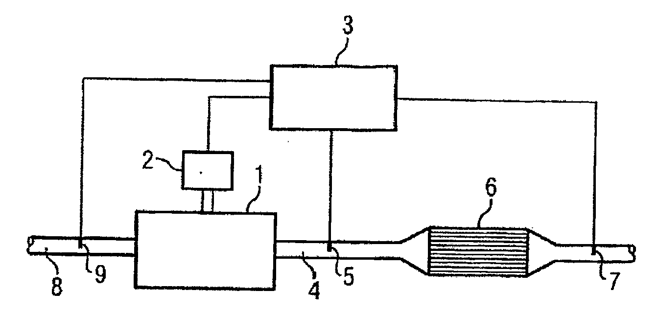
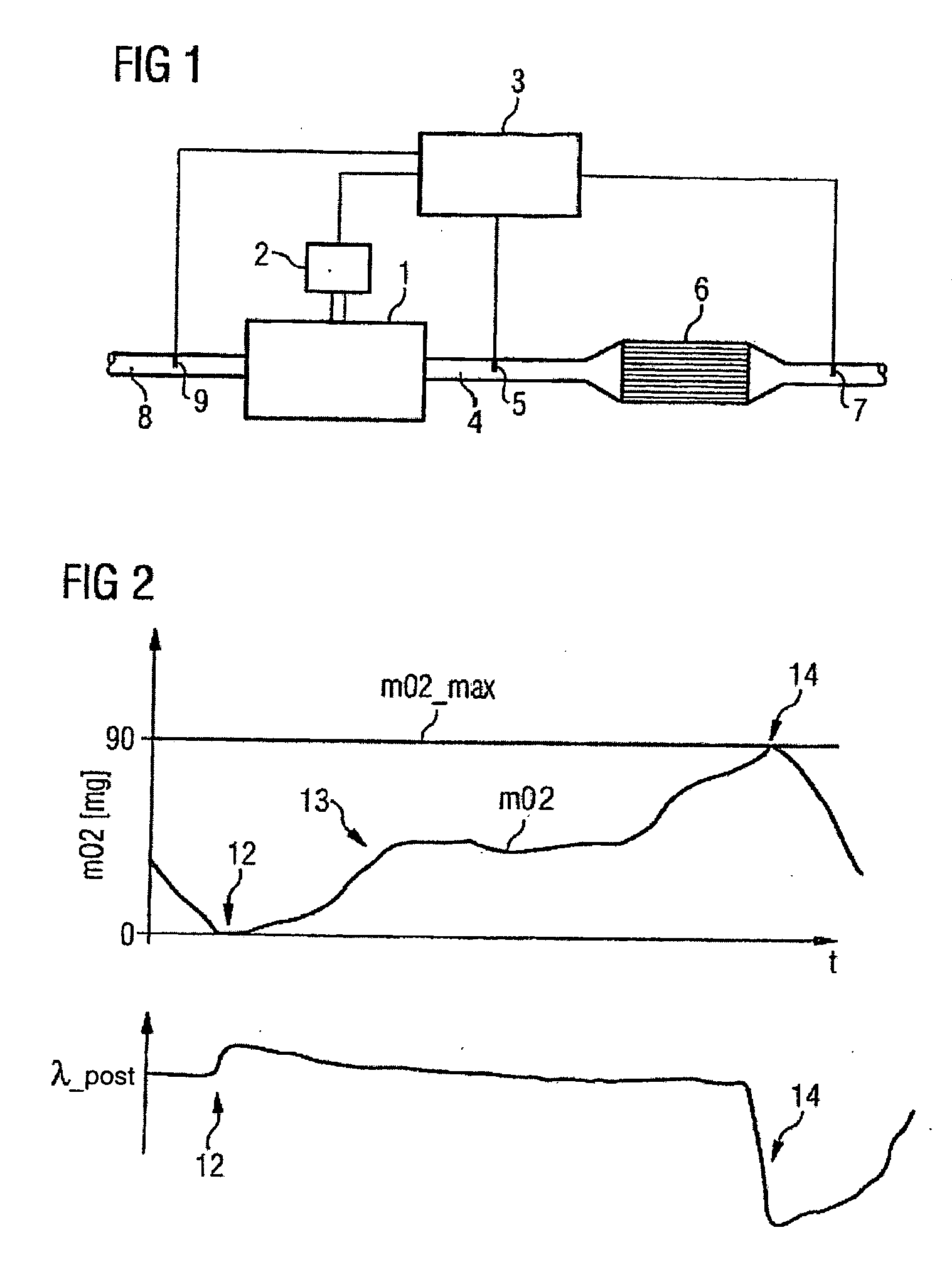
[0036]FIG. 1 shows an internal combustion engine 1 having a fuel-feed system [2] and a control device 3. The fuel-feed system 2 is controlled by the control device 3 via leads, which are not referenced further, and takes care of the fuel allocation needs of the internal combustion engine 1. A 3-way catalytic converter 6 is located in the exhaust tract 4 of said combustion engine 1. Provided upstream of the catalytic converter 6 is a pre-converter lambda probe 5 for performing lambda controlling and provided downstream of said converter is a post-converter lambda probe 7 for measuring the lambda value. Said pre-converter lambda probe 5 is a linear lambda probe, while what is termed a binary lambda probe is used here as the post-converter lambda probe 7 in which the output voltage in the range lambda=1 virtually jumps from, for instance, below 100 mV in the case of lean mixtures (lambda>1) to over 0.7 V in the case of rich mixtures (lambda3. In the intake tract 8 is an air-mass sensor...


PUM


Abstract

The invention relates to a method for determining the actual oxygen load of a 3-path catalyst of a lambda-controlled internal combustion engine, whereby a value for the actual oxygen load is calculated from the signal of a pre-catalyst lambda probe and the measured air mass flow rate by integration over time, whereby the post-catalyst lambda probe is initialized when the signal is interrupted.

Description

CROSS REFERENCE TO RELATED APPLICATIONS[0001]This application is the US National Stage of International Application No. PCT / EP2004 / 053283, filed Dec. 6, 2004 and claims the benefit thereof. The International Application claims the benefits of German Patent application No. 10 2004 009 615.5 filed Feb. 27, 2004. All of the applications are incorporated by reference herein in their entirety.FIELD OF THE INVENTION[0002]The invention relates to a method for determining current oxygen loading of a 3-way catalytic converter of a lambda-controlled internal combustion engine having a linear pre-converter lambda probe connected upstream of the catalytic converter, a post-converter lambda probe connected downstream of the catalytic converter, and a device for measuring the air-mass flow rate. The invention is furthermore directed toward a number of methods for regulating, controlling, and / or monitoring the exhaust treatment of a lambda-controlled internal combustion engine that use the values ...

Claims


Application Information

Patent Timeline
25 Dec 2008
Publication
US20080314023A1
IPC
F01N3/20; G01M15/10; F02D41/26; F01N11/00; F02D41/02; F02D41/14
CPC
F01N11/007; F01N2430/06; F02D41/0295; F02D41/1441; F02D2200/0814; F02D2200/0816; Y02T10/47; Y02T10/40
Inventors
POHMERER, WOLF-DIETER; RENZ, VOLKER