Solar augmentation system

a photovoltaic cell and solar energy technology, applied in the field of photovoltaics, can solve the problems of increasing the cost of solar energy storage, reducing the efficiency of single crystal silicon pv cells, and limiting the efficiency of conventional pv solar cells

Inactive Publication Date: 2008-12-25
HNUPHOTONICS
View PDF5 Cites 43 Cited by
  • Summary
  • Abstract
  • Description
  • Claims
  • Application Information

AI Technical Summary

Benefits of technology

[0026]Accordingly, the present invention is directed to a solar panel condenser that substantially

Problems solved by technology

The output of a conventional PV solar cell is limited to approximately 10% efficiency and as much as 17% to 20% in high end single crystal silicon solar panels.
Single crystal silicon PV cells have a higher efficiency than polycrystalline silicon; however, they are considerably more expensive.
Lower cost poly-crystal silicon material is now being used in these traditional PV cells, but at the cost of lower efficiency.
These research projects use very expensive multiple layer PV material that may not reach the consumer for many years to come.
The low efficiency (10-20%) that exists in PV solar cell technology is attributed to a narrow spectral range of solar radiation (FIG. 1) incident on the solar cell that is absorbed, thus resulting in usable electric current.
Shorter wavelengths in the ultraviolet and blue range are more readily absorbed by the semi-conductor; as a result higher energy photons do not reach the d

Method used


Image

  • Solar augmentation system
  • Solar augmentation system
  • Solar augmentation system

Examples


Embodiment Construction

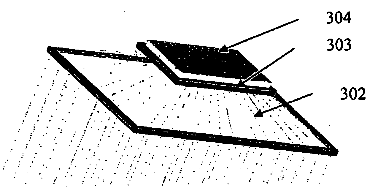
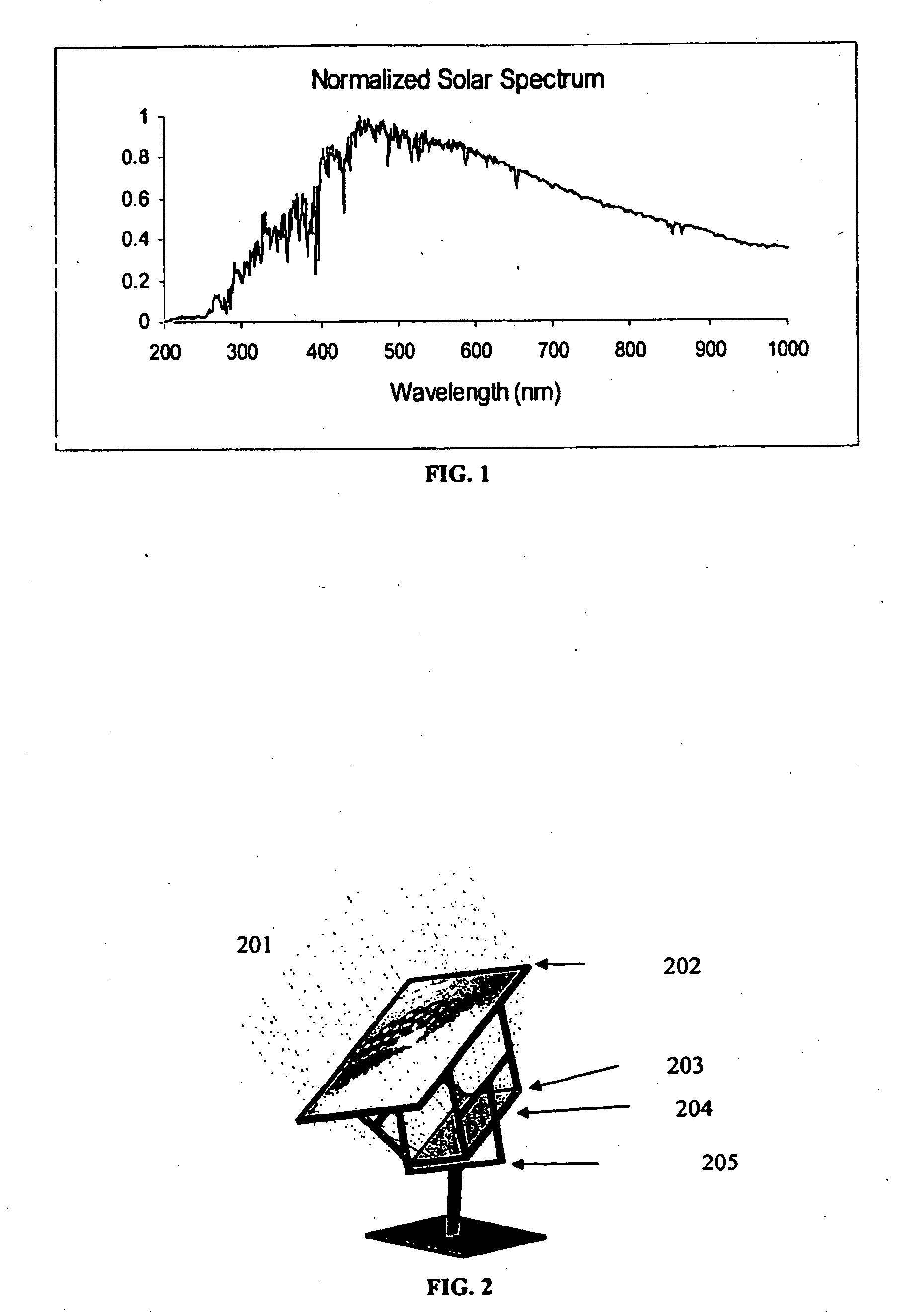
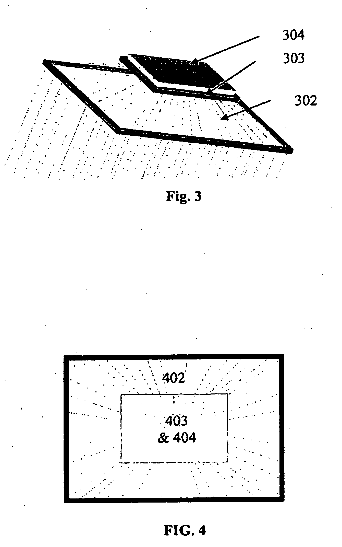
[0057]Reference will now be made in detail to the preferred embodiments of the present invention, examples of which are illustrated in the accompanying drawings. FIG. 2 is an embodiment of the solar panel condenser apparatus that incorporates an optical condenser that is larger in collection aperture than the solar cell. The optical condenser (or solar condenser optic) can increase the effective area of the solar cell by a factor of about 2, preferably about 3, or more preferably about 4 (or any practical magnification ratio), therefore increasing the number of photons contributing to photo-generated electrons or usable current.

[0058]Solar energy does not generate sufficient current in typical solar cells to raise the material into saturation condition. Accordingly, use of a larger collecting optic can result in increased current output. As is evident from Equation 2, the increase in current, which can result from using an optical condenser, is linear over a large range prior to sat...


PUM


Abstract

The present invention relates to a solar panel condenser apparatus that includes an optical condenser and a photovoltaic cell. The optical condenser may be two or more stages of Fresnel lenses. The optical condenser may also include one or more optical devices to separate sunlight into frequency bands so that light of different frequency bands falls on photovoltaic cells appropriate to the frequency band.

Description

RELATED APPLICATION[0001]This application claims priority of copending Provisional Application No. 60 / 907,404 filed on Mar. 30, 2007; U.S. application Ser. No. 11 / 512,418 filed Aug. 30, 2006; and U.S. application Ser. No. 11 / 889,369 filed on Aug. 13, 2007; the entire contents of which are hereby incorporated by reference.INCORPORATION-BY-REFERENCE OF MATERIAL SUBMITTED ON A COMPACT DISC[0002]Not applicable.SEQUENCE LISTING[0003]Not applicable.BACKGROUND OF THE INVENTION[0004]1. Field of the Invention[0005]The present invention relates generally to the field of photovoltaics, and more specifically to an apparatus for increasing the power output of photovoltaic cells.[0006]2. Description of Related Art[0007]A solar cell is a semiconductor device that converts incident photons from the sun (solar radiation) into useable electrical power. The general term for a solar cell is a photo-voltaic (PV) cell. The output of a conventional PV solar cell is limited to approximately 10% efficiency ...

Claims


Application Information

Patent Timeline
IPC IPC(8): H01L31/042
CPCF24J2/085H01L31/02167H01L31/0725H01L31/0547H01L31/0543H01L31/0549Y02E10/52F24S23/31
Inventor O'CONNELL, DANBORN, TERRY
Owner HNUPHOTONICS
Why Eureka
Try Eureka