Hybrid electric vehicle

a hybrid electric vehicle and electric vehicle technology, applied in the direction of electric generator control, motor/generator/converter stopper, dynamo-electric converter control, etc., can solve the problems of motor-generator not working as a starter for an engine, motor cannot be driven, and the approach used is disadvantageous

Inactive Publication Date: 2008-12-25
MAZDA MOTOR CORP
View PDF3 Cites 29 Cited by
  • Summary
  • Abstract
  • Description
  • Claims
  • Application Information

AI Technical Summary

Benefits of technology

[0004]This example discloses a hybrid electric vehicle configuration that uses a diode rectifier to reduce the loss of electric energy generated by the system by rectifying current generated by a motor-generator driven by the engine and then driving a motor connected to a vehicle driving system.
[0005]When an output current from the motor-generator is rectified by the diode rectifier as disclosed in this related reference, the loss of electric energy generated by the system can be reduced.
[0008]Therefore, there is a need for providing a hybrid electric vehicle that can make effective use of an inverter to operate with higher efficiency.

Problems solved by technology

However, the inventor herein has recognized a disadvantage with the approach used in this related reference.
Specifically, since a diode rectifier passes a direct current, a motor-generator will not work as a starter for an engine due to the unidirectional flow of the direct current.
However, this approach introduces another problem; specifically, a motor cannot be driven during an engine start when a driving motor is required.
Further, since a capacity requested for an inverter changes significantly depending on vehicle operating conditions, when the vehicle is operating under a certain condition where the inverter is operated with an output much smaller than a rated output, the inverter cannot be used efficiently due to a decreasing inverter loading rate.

Method used


Image

  • Hybrid electric  vehicle
  • Hybrid electric  vehicle
  • Hybrid electric  vehicle

Examples


first embodiment

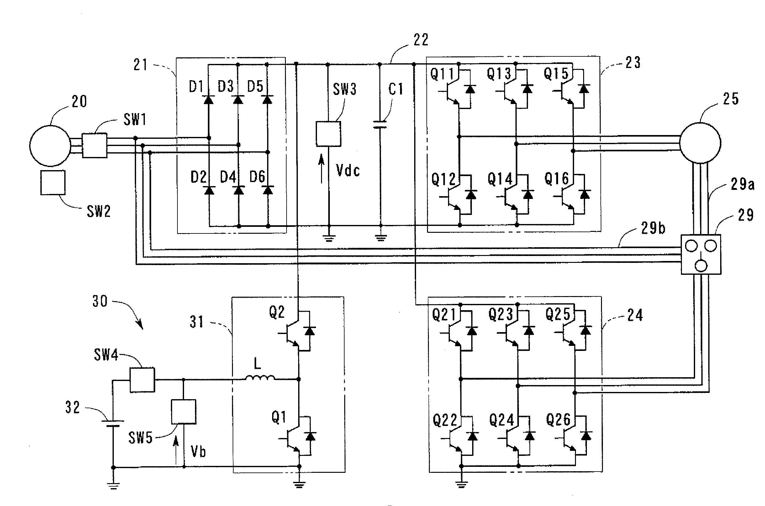
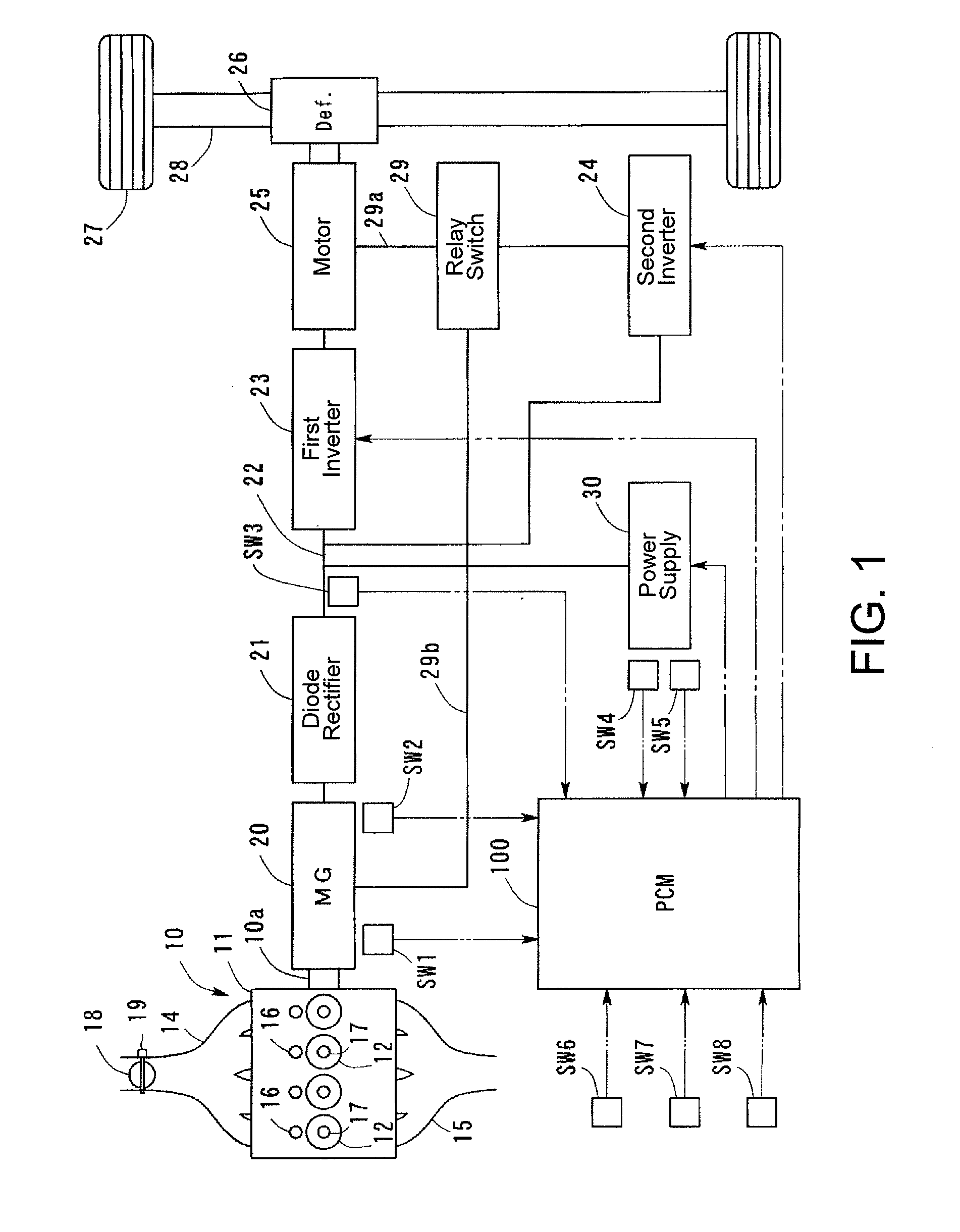
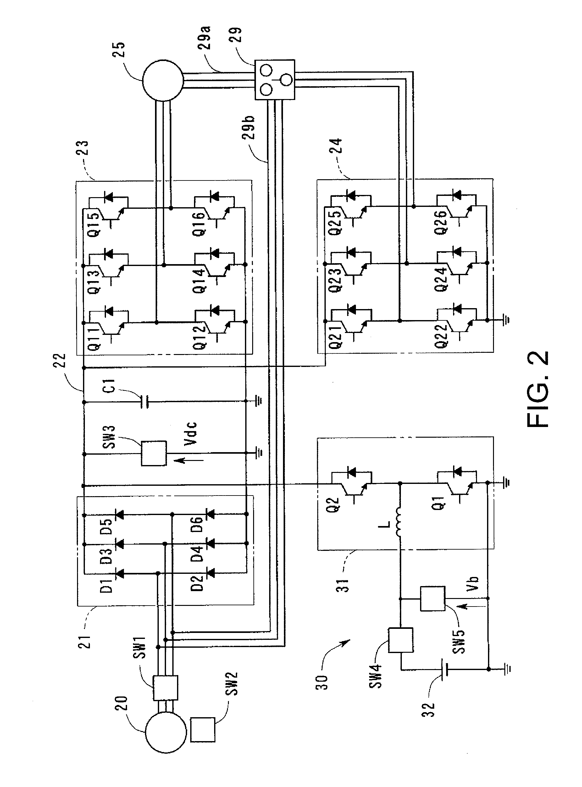
[0042]FIG. 1 is a schematic block diagram of a hybrid electric vehicle according to an embodiment of the present invention, and FIG. 2 is a circuit diagram showing a particular portion of FIG. 1. Referring first to FIG. 1, the vehicle is a series-hybrid-electric vehicle in this embodiment, which typically includes an internal-combustion engine 10, and an electric motor generator 20 that is driven by the engine 10.

[0043]In this embodiment, the engine 10 is a multi-cylinder four-cycle engine, which includes a body 11, a substantial portion of which is constituted with a cylinder head and a cylinder block, two or more cylinders 12 formed inside the body 11, an air-intake manifold 14 that introduces fresh air into each cylinder 12, and an exhaust manifold 15 that discharges exhaust gas from each cylinder 12 after combustion. Each cylinder 12 includes a fuel-injection valve 16 and a spark plug 17. A piston is provided inside each cylinder 12 so that it reciprocally moves to drive a crank...

second embodiment

[0080]FIG. 8 is a circuit diagram according to another embodiment of the invention, similar to that shown in FIG. 2. In this embodiment, the relay switch 29 that can switch the second inverter 24 between three channels is adopted as the switching module, and a third power feed line 29c for loading is connected to the relay switch 29. The feed line 29c is connected to electric equipment 50, and an ON / OFF relay switch 51 is connected between the electric equipment 50 and the relay switch 29.

[0081]The electric equipment 50 may include an on-board power supply (AC100V), an air-conditioning unit for vehicle cabin, etc. In an operating range where the second inverter 24 is not necessary to supply power to the motor 25, the electric equipment 50 is supplied with power from the second inverter 24 by switching operation of a relay control module (e.g., corresponding to the relay control module 111 of FIG. 3). Therefore, it is possible to improve efficiency of the inverters 23 and 24 and main...

third embodiment

[0083]Next, still another embodiment of the present invention will be explained. FIG. 9 is a schematic block diagram of the hybrid electric vehicle according to this embodiment. For the vehicle of this embodiment, an electric motor generator 20, a DC bus line 22, and an inverter 23 constitute a first power feed channel of three phases. In addition, a bypass circuit 40 that constitutes a second feed channel in parallel with the first feed channel is provided between the motor generator 20 and the motor 25.

[0084]In this embodiment, the bypass circuit 40 is constituted with AC bypass switches 41-43 provided corresponding to phases of the motor generator 20 (u-phase, v-phase, and w-phase), respectively.

[0085]Referring also to FIG. 10, which is a circuit diagram showing a detail of the AC bypass switches 41-43 shown in FIG. 9, the AC bypass switches 41-43 are implemented with semiconductor switches, each constituted with a pair of transistors 41a-43a for one current direction that contro...


PUM


Abstract

A hybrid electric vehicle includes, in one example, a motor-generator driven by an engine to generate alternating current, wherein the motor-generator is further configured to start the engine, a motor for driving the vehicle, a diode rectifier to rectify alternating current generated by the motor-generator, an inverter connected to a feed circuit between the diode rectifier and the motor to convert direct current in the feed circuit into alternating current, a power supply connected to a line connecting the diode rectifier with the inverter, a first feed circuit to supply current to the motor to drive the vehicle through the diode rectifier and the inverter in series a second feed circuit to connect the motor-generator with the power supply while bypassing at least the diode rectifier, and an alternating current converter provided in the second feed circuit.

Description

TECHNICAL FIELD[0001]The present description relates to hybrid electric vehicles. More particularly, the description pertains to a hybrid electric vehicle configuration suitable for a series hybrid electric vehicle.BACKGROUND AND SUMMARY[0002]The series hybrid electric vehicle designates a vehicle configured to drive an electric generator by an internal combustion engine (engine), to supply electric power from the electric generator to a motor, and to drive drive-wheels by the motor, as disclosed in US 2007 / 0137908 A1, as an example. In a series hybrid electric vehicle, the engine is dedicated to generating electric energy; the mechanical energy generated by the engine is not directly transmitted to the drive-wheel, in contrast to a parallel hybrid electric vehicle, where some mechanical energy generated by an engine is directly transmitted to a drive-wheel.[0003]One example of a hybrid electric vehicle is described by Japanese Unexamined Patent Application Publication No. 2005-2043...

Claims


Application Information

Patent Timeline
Patent Type & Authority Applications(United States)
IPC IPC(8): H02P9/08H02P27/06B60L50/13
CPCY02T10/6217B60L50/61B60L15/007B60L2210/14B60L2210/30B60L2210/40B60L2240/12B60L2240/421B60L2240/429B60L2240/441B60L2240/445B60L2240/529B60L2240/547B60L2240/549B60L2250/26Y02T10/7241Y02T10/7225Y02T10/645Y02T10/7077B60K2006/268Y02T10/62Y02T10/64Y02T10/70Y02T10/72Y02T10/7072
Inventor YONEMORI, KEISEO, NOBUHIDESAITO, KOHEIAKAGI, HIROFUMIFUJITA, HIDEAKI
Owner MAZDA MOTOR CORP
Why Eureka
Try Eureka