Cutting method

a cutting method and cutting technology, applied in the field of cutting methods, can solve the problems of inability to use a machine tool having an atc (automatic tool changer), limited method, and limited use of cutting chips under the cover which covers a cutting tool and a holder. efficient removal, quick removal, low energy

a cutting method and cutting technology, applied in the field of cutting methods, can solve the problems of inability to use a machine tool having an atc (automatic tool changer), limited method, and limited use of cutting chips under the cover which covers a cutting tool and a holder. efficient removal, quick removal, low energy

US20090000441A1Inactive Publication Date: 2009-01-01OKUMA CORP

Image

  • Cutting method
  • Cutting method
  • Cutting method

Examples


Embodiment Construction

[0023]One embodiment of a cutting method of the present invention (using a ball end mill as a cutting tool) will be described below referring to the drawings.

[Structure of a Ball End Mill]

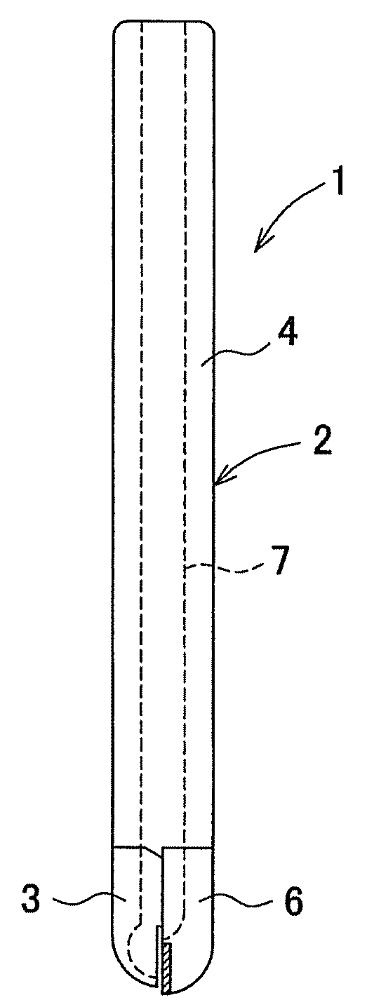
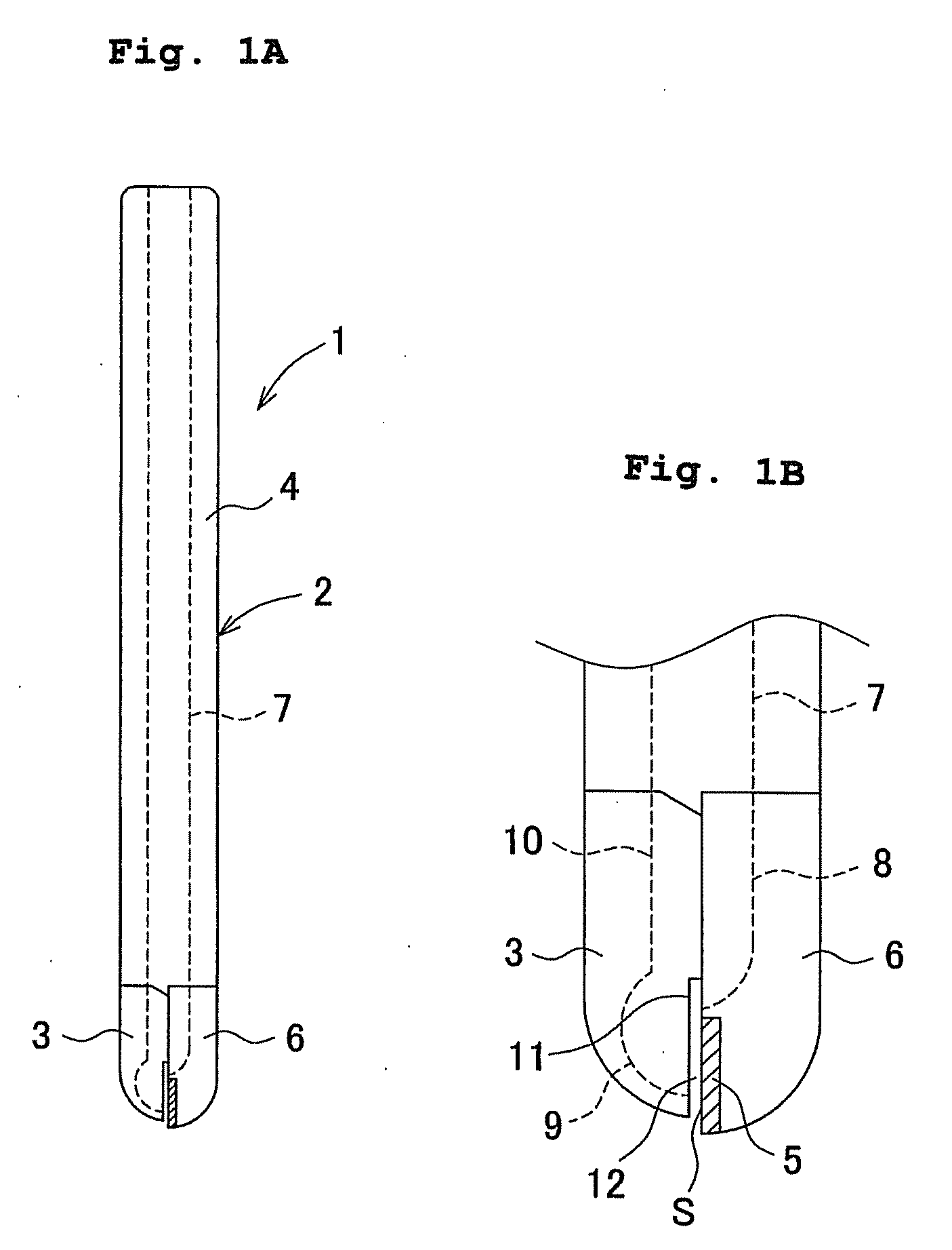
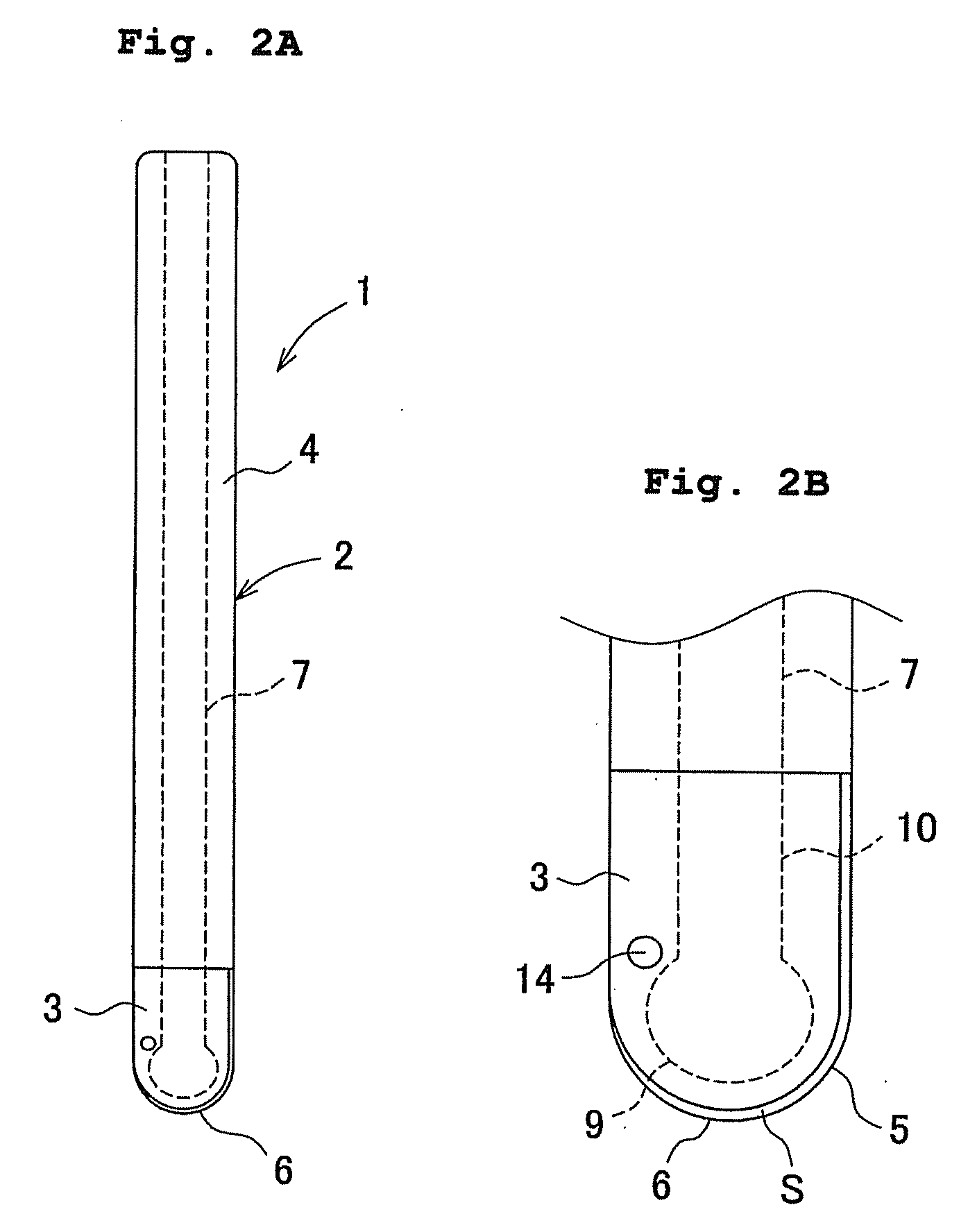
[0024]FIGS. 1 to 3 illustrate a front face, a left side face and a bottom face of a ball end mill. A ball end mill 1 includes an end mill body 2 made of a metal (a cemented carbide), and a cover 3 made of a metal (a cemented carbide). The end mill body 2 includes a head part integrally provided at a tip of a shank 4, and the length of the end mill body 2 is approximately 90 mm. The shank 4 is in a cylindrical shape having an approximately 10 mmφ and includes a suction passage (a cave) 7 having a cylindrical shape of an approximately 5 mmφ at a substantial center of the shank 4 (therefore, the cross sectional area of the suction passage 7 is about 19.6 mm2). Further, a head part 6 is in a shape that a semi-sphere is connected onto a tip of a semi-pillar of an approximately 10 mmφ (this shape is like...


PUM

PropertyMeasurementUnit
lengthaaaaaaaaaa
areaaaaaaaaaaa
pressureaaaaaaaaaa

Abstract

An object is to provide a cutting method capable of efficiently removing cutting chips around a cutting point with a little electric power, and cutting a work with high accuracy.A ball end mill having a slit shaped-opening part at a portion adjacent to a rake face of a cutting edge and internally having a suction passage is used, and a work in which a cutting liquid is previously coated on an inclined face is cut while the cutting liquid is sucked in the area around the cutting edge from the opening part through the suction passage. As a result of this, in case of using non water-miscible cutting oil, when the cutting liquid in the area around the cutting edge is sucked from the opening part, a cutting power decreasing rate is higher than a case where the suction is not carried out.

Description

BACKGROUND OF THE INVENTION[0001]This application claims the entire benefit of Japanese Patent Application No. 2007-173151 filed on Jun. 29, 2007 the entirety of which is incorporated by reference.FIELD OF THE INVENTION[0002]The present invention relates to a cutting method for cutting a work, which is made of a metal or the like, by using a cutting tool having a cutting edge.DESCRIPTION OF THE BACKGROUND ART[0003]In a case of cutting a work made of a metal or the like by using a cutting tool having a cutting edge, cutting chips are generated during cutting of a work (a substance to be cut). When cutting is carried out where the cutting chips are accumulated on a surface of the work, a cutting edge is caught in the accumulated cutting chips resulting in damage of the cutting edge or a decrease of accuracy of cutting work. Further, since the cutting chips are heated at a high temperature due to friction, the cutting edge or the work is thermally deformed, which decreases cutting accu...

Claims


Application Information

Patent Timeline
01 Jan 2009
Publication
US20090000441A1
IPC
B26D3/00
CPC
B23C5/1009; B23C2230/045; B23C2230/08; B23C2250/12; B23Q11/0046; Y10T409/303808; Y10T408/46; Y10T409/304032
Inventors
HASEBE, TAKAO; WAKAOKA, SHUNSKE